Summary of Enhanced 5/2-day Central Heating Programmer with serial computer interface using PIC16F628A
This project is a flexible, remote-controlled central heating programmer using a Microchip PIC 16F628A microcontroller. It features independent control for heating and hot water with 10 programmable entries supporting weekday, weekend, or daily schedules. The system includes a front panel for local operation and an RS232 serial interface for remote PC control via CLI. Designed as two separate units (relay board and intelligent programmer), it allows low-voltage connections over CAT5 or alarm cable to locate the controller away from the boiler while ensuring battery-backed timekeeping and settings retention during power outages.
Parts used in the Enhanced 5/2-day Central Heating Programmer:
- Microchip PIC 16F628A microcontroller
- Two relays for switching mains power
- RJ45 socket for CAT5 cabling connection
- 2.1mm DC power socket
- External 9~12V DC power adapter
- 9-pin D socket for PC serial interface
- Liquid Crystal Display (LCD)
- Front panel switches
- CAT5 UTP cabling or 6-core alarm cable
- Battery backup for Real Time Clock
Overview
This project has come about from my desire to control my home heating from work. As I have a VPN between work and home a straightforward relay controlled from a PC would seem the easiest solution. However I also wanted a control unit that I could operate in the house without resorting to the computer. For example, I get up late and the heating is off, I just want to hit a button and turn it on. In fact the programmer shown on this page is now next to my bed so I can turn the heating on before I get up late, and also switch it off if I turn in early, which helps save on the fuel bills J
Features
-
Independent control for heating and hot water.
-
10 flexible program entries.
-
Programs can be set to operate Mon-Fri / Sat-Sun / Mon-Sun.
-
Manual advance for water and heating
-
Water and heating can be independently set to manual or programmed control.
-
Operation and setup from front panel or remote serial CLI
-
Battery backup for Real Time Clock (RTC), program settings and manual control.
-
Programmer can be located remotely from boiler using low voltage signals over CAT5 or 6-core alarm cable.
-
RS232 serial interface with command line interface allows full control and setting from any computer.
-
Front panel control can be locked-out from serial CLI
-
Based on Microchip PIC 16F628A microcontroller
This programmer has been designed for use with a domestic heating boiler. It provides outputs via two relays to control the supply of Hot Water and Heating. There are 10 program entries available and each one can control the heating and water independently. The programmer allows manual advance of the heating and water and disabling of program control, useful if you’re going away for a few days and want to leave the heating and water off. As well as providing normal front panel switch control of the heating and water, the programmer also features a serial terminal interface that allows it to be operated remotely from a PC running a Terminal Emulator.
The program entries can be set to switch weekdays only, weekends only or everyday but not individual days. I believe a programmer that can switch weekdays or weekends is a 5/2-day programmer so I would call mine a 5/2/7 day programmer since it can do the whole week as well. However, a 7-day programmer is one that can do individual days so I’ve settled on calling mine an Enhanced 5/2-day programmer.
The programmer and boiler control relays are contained in separate units so that the relays can be located close to the boiler while the programmer itself can be located anywhere in the house using low voltage connections back to the relay unit. The connection between the programmer and relay unit requires six wires for power, serial data and relay controls making it possible to use 6-core alarm cable or, as I have done, operate it over the CAT5 UTP cabling installed throughout my house. Of course it’s quite simple to build it as a single unit if that suits the application. There is also no reason why you can’t make the serial interface connection local to the programmer in which case you only need 4 wires for power and relay controls.
If you don’t require the remote computer CLI the programmer is fully functional using just the front panel and likewise, if the front panel isn’t required, it can be fully controlled from the serial interface and the LCD and switches omitted from the hardware.
Software
The latest version of the programmer ready .HEX file is provided here.
|
Firmware Version 2.0.2 28 May 2005
|
Developed using MPLAB V7.10 and Oshonsoft PIC Simulator IDE. Assembled with MPASM v04.00
The software is fully functional and the system as described on this web page is currently working with my domestic heating system. I’ve been using prototypes since March 2005. The latest code, Version 2.0.2, has been running since 28 May 2005. As of 17 January 2011 it’s still working and has proved to be 100% reliable.
This is the final version of the code. I’m not going to develop it any further since the programmer now implements all the features I want and works as I intended. I will do maintenance code releases to fix any software related bugs / issues reported to me.
Known issues
-
no known critical issues.
-
Some CLI commands allow superfluous text on the line after the command. The command executes correctly and any superfluous text is ignored.
- Please send any bug reports to Contact us:

Functionality as designed
-
The current relay output and manual mode settings are stored in NVRAM. In the event of a power failure these are restored when the power resumes. If a programmed setting should have applied at a time during the power outage, it will not get applied when the power is restored. The saved settings that were active at the time of the power failure will be reapplied.
-
When in front panel setup mode, no programmed outputs will be activated. If a programmed setting should have applied while the programmer was in setup mode, it will not get applied on exit.
-
On power up the programmer sends a VT100 [ESC] c command to the terminal to reset it. This may cause extraneous characters to be displayed or other issues on a non VT100 emulator.
-
Time is displayed / entered in 24 hour format only.
-
Serial interface operates at 9600bps, 8 bits, 1 stop, No parity. Baud rate is not configurable
-
When in front panel setup mode the serial CLI is disabled.
Code Revisions
V2.0.3
-
As version 2.0.2 code but without the CLI diagnostic commands. These commands where implemented from an include file which has simply been omitted during assembly for V2.0.3.
V2.0.2
-
Enabled the PIC Watch Dog Time (WDT) and added supporting code.
-
New command ‘dw’ shows number of Watch Dog timeouts that have occurred since power-up. These should not occur if the programmer is functioning correctly, if they do this alerts you to a potential problem.
-
Implemented front panel setup functions. Allows time to be set. Program entries to be viewed, cleared, entered and edited.
-
Changed handling of serial CLI input buffer overflow. The behavior is now consistent with handling of unknown commands.
-
The CLI ‘p’ command now shows output control for Hot Water followed by Central Heating. This is the opposite way round to firmware before V2.0.0
V1.9.1
-
Added CLI command to enable / disable front panel control. This has been added to allow the front panel to be locked out when using automated control of the unit from the CLI. It also provides a way to stop my girlfriend from turning the heating on all the time:-)
-
CLI relay control command letter has been changed from ‘t’ to ‘u’.
-
The relay control and manual mode CLI commands worked by inverting the current setting. This has now changed so that the setting for on/off or manual/programmed is explicitly specified on the command line.
-
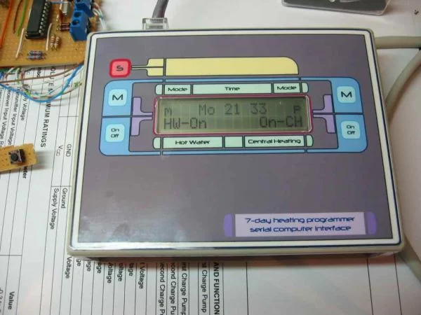
Moved the on/off text for heating and water on the LCD to the extreme ends of the display. This is to allow the display of the text ‘Locked’ when the front panel is disabled.
V1.9
-
Prior to FW V1.9 the LCD display had the text CH- and -HW on the second line but as the programmer is now cased and the front panel artwork has legends on it, this text has been removed from the V1.9 code.
-
The manual mode status was indicated with the characters ‘m’ and ‘p’. This has now been replaced by the text ‘Man’ and ‘Prg’
-
Added CLI function to send a VT100 [ESC] c command to the terminal to reset it.
-
Send VT100 [ESC] c command to the terminal at power-up.
-
Added command to return an ASCII hex byte with the current status of the relay outputs and manual mode settings. For use with automated control of the CLI.
-
Improved the CLI ‘p’ command entry format and parsing.
-
Made program control for CH and HW outputs fully independent by adding a no-change flag and enabling this feature within all related functions.
Hardware
The hardware for the programmer comprises two units. The first contains the two relays that switch the mains power to control the boiler. This also has an RJ45 socket to allow connection into a CAT5 cabling system that takes power, serial data and relay control input signals to the second unit, an intelligent programmer. There is also a 2.1mm DC power socket that is used to connect an external 9~12V DC power adapter. This supplies power to the relay board and the programmer controller. A 9-pin ‘D’ socket provides connectivity to a PC serial interface.
For more detail: Enhanced 5/2-day Central Heating Programmer with serial computer interface using PIC16F628A
- How can I operate the heating remotely?
The programmer features an RS232 serial interface with a command line interface that allows full control and setting from any computer running a Terminal Emulator. - Can the heating and hot water be controlled independently?
Yes, the programmer provides independent control for heating and hot water with 10 flexible program entries where each can control them separately. - What type of cabling is required for the remote setup?
The connection requires six wires for power, serial data, and relay controls, making it possible to use 6-core alarm cable or CAT5 UTP cabling. - Does the unit retain settings during a power failure?
Current relay output and manual mode settings are stored in NVRAM and restored when power resumes, though scheduled events missed during the outage will not be applied retroactively. - How do I set the schedule for weekdays versus weekends?
Programs can be set to operate Mon-Fri, Sat-Sun, or Mon-Sun, allowing for weekday-only, weekend-only, or everyday operation. - Is it possible to lock out the front panel controls?
Yes, the front panel control can be locked-out from the serial CLI to prevent manual operation while using automated control. - What firmware version is recommended for diagnostic commands?
Version 2.0.2 supports the CLI diagnostic commands, whereas Version 2.0.3 does not include these diagnostic features. - How is the time format displayed on the device?
Time is displayed and entered in 24-hour format only on the programmer. - Can the programmer be built as a single unit?
Yes, although designed as separate units for remote placement, it is quite simple to build it as a single unit if that suits the application. - What happens if I enter superfluous text in a CLI command?
The command executes correctly and any superfluous text on the line after the command is ignored.