Summary of ECE 4760 Glove Controlled Tilt Maze
This article describes a glove-controlled tilt maze game where users navigate a ball by tilting the board via an accelerometer and opening trapdoors using finger sensors. The system features a TFT display for instructions, IR sensors to detect ball drops, and servos controlled via a demultiplexer due to pin limitations. The project emphasizes real-time processing, low-pass filtering for stability, and safety measures like electrical insulation.
Parts used in the Glove Controlled Tilt Maze:
- MPU-6050 Accelerometer
- Perfboard (cut into 5 pieces)
- Servos (7 total: 2 for tilt, 5 for trap doors)
- Demultiplexer (Demux)
- IR LED
- IR Receiver Diode
- Resistors (1 kOhm)
- TFT Display
- PIC Microcontroller
- Port Expander
- Push Button
- 3D Printed PLA parts
- Laser Cut Birch Wood parts
- Funnels
Introduction
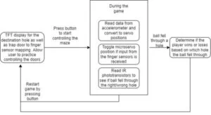
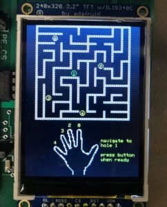
Our project is a tilt maze game controlled by a glove worn by the user, which contains an accelerometer as well as sensors for each finger. The tilt of the maze is continuously updated in accordance with the position of the user’s hand. The maze itself contains several holes with servo-controlled trapdoors obstructing the path, which can be opened and closed based on the input from the finger sensors. At the start of each round, a display on the TFT screen will illustrate the destination hole and indicate which trap door each finger can control. The user will be given time to practice controlling the doors before starting the game and gaining control of the maze tilting. If the ball falls through one of the other holes, this results in a failed round. Otherwise, once the ball is navigated to the correct location, the screen will indicate a success. At the end of the round, the same button can be pressed again to renavigate back to the start screen, where a new destination will be indicated on the screen.
We wanted to create a game that was fun to play and that incorporated various different features, such as the IR sensors, servos and finger sensors. We were also excited to build a physical product that could be interacted with.
Video Demonstration
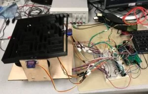
The Entire Project

Game Overview
- TFT displays a start screen illustrating the destination hole as well as the mapping between the finger sensors and remaining trap doors
- Practice controlling the trap doors, then press a button to start the game
- Move the ball through the maze by tilting the glove; the ball falling through the wrong hole results in an immediate fail
- Once the ball reaches its destination, the TFT screen displays either success or failure
- Press the button to go to the start screen and begin a new game
The basic idea of this game has already been used several times, so we wanted to build on it to increase the complexity and make it our own design. This is why we added the trap door aspect to the game; in doing so we also needed to include detection for which hole the ball fell through. One challenge we faced with this project was the shortage of pins since we wanted to control seven servos independently from one another, as well as have five IR detection circuits and four finger sensor inputs. As a result, we had to make use of the port expander in order to include all of our desired sensors, as well as a demux to be able to control all the servos. The port expander communicates with the PIC over SPI, which is rather slow, so setting and clearing bits of the port expander introduced more overhead. However, this tradeoff enabled us to include these various hardware components, and since we did not have strict timing deadlines in our code, this was a worthwhile adjustment.
Regarding copyrights, since the main concept for this game has already been reused by several different companies and apps, we believe that there are no issues regarding copyright. Additionally, this article specifically states that a similar game (Labyrinth) does not have a copyright in the United States. Our gameplay is also significantly different than that of the designs already created.
The Control Glove
Accelerometer
The MPU-6050 accelerometer we used communicates with the PIC over i2c. We fortunately discovered a previous ECE 4760 project (3DOF Stewart Platform) that used the same accelerometer we had, so we were able to adopt part of their code to read the accelerometer data. Their code contained several helper functions such as i2c_read, which enabled us to read various registers containing the data we wanted. The accelerometer values were updated in a thread that ran every 1ms. This was also where we calculated the values being sent to the motors. Initially, we were having problems with jitter, since the accelerometer readings were sensitive and fluctuated quite significantly. To address this, we created filter_x and filter_y variables, which low-passed the readings. We then used the filtered readings to create a direct mapping between the accelerometer values and pwm signal.
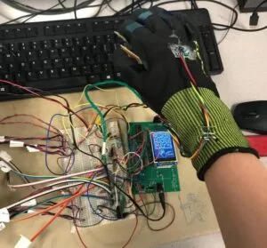
Finger Sensors
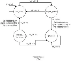
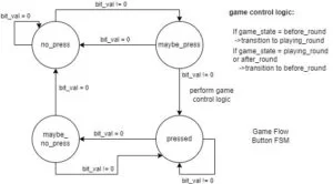
For the finger sensors, we cut up a perfboard into 5 pieces (one for each finger) to be used as contact plates. The plate on the thumb is connected to 3.3V and the plates on the other fingers are conencted to an input pin. These sensors essentially behaved as buttons, where connecting the plate on a finger to the plate on the thumb closed a switch and pulled the voltage on the pin high. The four inputs were connected to pins 0-3 on Port Y. In order to address problems regarding debouncing, we implemented a thread to poll the state of each pin every 30ms (determined by human reaction speed) and utilized a button FSM for each input. bit_val is the value of one of four pins on the port expander corresponding to the specific finger we want to check.
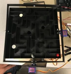
The Maze
Physical Structure
The physical structure of our maze was made out of both 3D printed (from PLA plastic) and laser cut (from 1/8 inch birch wood) pieces, which we designed ourselves in Autodesk Fusion 360. We 3D printed the intricate parts that would be difficult to laser cut or assemble from laser cut pieces, such as the cones, servo doors, and maze itself. We laser cut the large and more basic parts that would take a 3D printer too long to print or would exceed the bed size of the 3D printer, such as the base for our maze. The CAD files (in STL and DXF formats) can be found in the Appendix page of this website.
Servos
The servos are controlled using PWM, which we implemented using output-compare peripherals on the PIC. We configured the output-compares to PWM mode, then connected them to timer2 and mapped them to different pins on the PIC. Then, in the ISR for timer2, which generated an interrupt every 1 millisecond (44,000 clock cycles), we wrote the updated pwm values, which were calculated in the accelerometer thread. We used a timer interrupt instead of a regular thread because we wanted to update the PWM duty cycles at precise intervals.
For our game, we needed to control a total of seven servos; two for the tilt of the maze and five for the trap doors. However, the PIC only has five output-compare peripherals and each unique pwm signal requires its own. To get around this issue, we noted that the five servos for the trap doors will never need to move at the same time (due to the way in which we designed the game). This meant that we could output one pwm signal from the PIC, connect it to the COM OUT/IN pin of a demultiplexer, and use three additional pins for the demux select signal (labeled A, B and C in the diagram). Based on the select signal, the demux would send this pwm signal to one of the five servos.
IR sensors
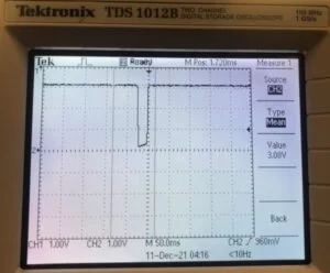
To implement ball detection, we placed an IR LED on one side of each hole, and an IR receiver diode in series with a resistor that goes to ground. A signal pin connected to the PIC is placed between the diode and resistor. The resistance of the IR receiver diode changes depending on whether it detects infrared light (high when no IR is detected and low when it is detected). When the ball falls through it momentarily prevents the light from reaching the sensor, causing the diode resistance to greatly increase and making voltage drop across the resistor change from 3.08V to about 0.2V. We found that a higher resistance value for the resistor in series with the IR receiver allowed for a higher change in voltage across it, which is why we replaced our original design using 330 Ohms with 1 kOhms.
The IR signal inputs are connected to pins 0-4 on Port Z of the port expander, where we configured interrupts for each of these five pins. In order to trigger an interrupt on the PIC, we attached an external interrupt to RPA2, the PIC pin that communicates with Port Z. However, this means that the ISR will be entered upon a change in value on any of the port expander pins with interrupts enabled, without a direct way of determining which specific pin caused the interrupt. To solve this issue, we added a function that reads the Port Z interrupt capture register (which stores the state of the port when the interrupt was triggered) so that we could compare the new port values to the previous ones and determine which one changed. Then, based on the value of the destination hole, we set a win_round flag which is used in the after_round game state to display the appropriate message.
TFT Display
To display the images on the TFT, we first converted our images to bitmaps using this website, then rewrote the tft_drawBitmap function in the tft graphics source file to draw rectangles for each pixel in the image. The size of this rectangle was passed in as a parameter so we could decide how much we wanted to scale the image by. Though it is rather slow to loop through each element in a bitmap and draw a rectangle for each pixel, we decided that this was an acceptable sacrifice due to the fact that we only need to print everything once. This means that it will not interfere with the timing of the game, since after the thread runs at the beginning, it is not scheduled again until the start of the next round.
Program Design
To control the game flow, we created a game state enum consisting of before_round, playing_round and after_round. We included a button in our circuit that, when pressed, would change the game state depending on the current game state, as illustrated in the figure below. To generate a random number for the destination, we utilized the ADC to generate a random seed. This involved taking two readings from a floating pin and summing them together, with the first reading left shifted by one and the second left shifted by 5. We then were able to call the rand() function and receive different random numbers upon resetting the PIC. To get a number between 0 and 4, we computed the randomized number mod 5. Using this number, we were able to create a direct mapping between each finger and the remaining doors.
Servo Calibration and Timing Considerations
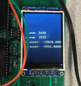
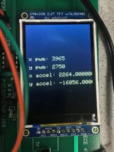
To calibrate the accelerometer, we measured the reading when the board was positioned vertically for all four positions (forward, backward, left, right); see images below. We then used these values to map the instantaneous accelerometer readings to a pwm value. The servos we used have a period of 20ms, and according to the data sheet, a 1ms on time corresponds to 0 degrees and a 2ms on time to 180 degrees. However, when working with the servos, we realized that the servo range was actually from about .8ms to 2.3ms.
The accelerometer readings were very sensitive, with the numbers containing fluctuation up to the hundreds decimal place, which created very obvious jitter in the servos and made the game unplayable. To accommodate this, we implemented a low-pass filter on the readings, and used the filtered values in our pwm calculations. We updated the accelerometer readings in a thread with a 1ms yield time, and updated the PWM signals in an ISR that triggered every 20ms. These values were chosen through experimentation since we wanted the servos to respond quickly to changes in the accelerometer position, but also did not want to interfere with our other threads, which utilized polling to detect button presses. The restart button and finger sensor threads both had a yield time of 30ms; this value was based on human reaction time with an additional margin of error, since we aren’t physically capable of completing two button presses within such a short period of time. Especially for the finger sensors, we wanted the response time to be as fast as possible so that the trapdoors could be toggled quickly, and we found that these values worked well.
Our calculations to convert the accelerometer readings to PWM involved adding an offset to bring the most negative accelerometer reading to 0, then multiplying this by the number of clock cycles corresponding to our desired servo range (1ms), and finally adding the minimum pwm on time. To further calibrate the servos, we added two different offsets to the x and y servos to make sure that the maze was perfectly horizontal when the accelerometer was placed flat on the table.
Changes in the IR sensor readings were detected using interrupts. As seen in the image below, when a ball falls through, the signal only goes low for about 25ms; if we were to implement IR detecting using a polling thread, it would have to run very frequently in order to ensure that change are consistently detected. We concluded that this would likely interfere with the timing of reading the MPU and updating the servo pwm values, and impact the responsiveness of the finger sensors. In addition, this change in signal is very clean and does not contain any oscillation or debouncing like the buttons that would necessitate polling. Utilizing interrupts also enabled us to capture the port value when the interrupt triggered, making the detection logic for determining which pin caused the interrupt very straightforward.
Our design did not contain any dangerous elements, but because the servos tended to behave quite unpredictably when uploading new code, we always made sure to unplug the power when making any modifications. In addition, since the finger sensors involve the user making an electrical connection with their hand, we made sure that they would be protected from any harm by selecting an electrically insulating glove and using low voltages. Regarding usability of our product, we acknowledge that this would be an even more difficult game to play for those that lack fine motor control in their hands, as well as those that are left-handed. However, this is unfortunately the nature of the gameplay, so we were unable to make accommodations for this.
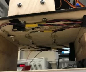
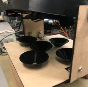
Conclusion
The design of our final product deviated slightly from what we had originally envisioned, but contained all of the elements that we had hoped to include. One major obstacle we encountered was incorporating the IR sensors into our design. We had originally planned to attach them directly to the bottom of the maze, but soon realized that we would not be able to manage the large quantity of wires in a way that would not inhibit the playability of the game. Therefore, we instead decided to elevate the maze platform and drill 5 holes in it, then place funnels over each of these holes to catch the ball when it fell through the maze. This allowed us to place the IR detection circuits underneath the platform, which gave us much more room to work with and also did not interfere with the gameplay. However, this detection strategy is not as accurate because there is a chance that the ball will not fall into the correct funnel or miss altogether, especially for the holes near the edges of the maze because the tilting causes it to cover a greater horizontal area. Therefore, if we were to improve our design, we would make the diameter of the funnels for the outer holes larger to decrease the probability of the ball missing.
Next time, we would try to think through our design more carefully at the start in order to avoid running into such design issues at the end. However, aside from this we were quite happy with the outcome, as we accomplished everything we had planned to.
It is worth noting that although the vast majority of the work was developed by us, not everything in the project is our work. Specifically, regarding intellectual property, the layout of the maze was based off of this image which we have permission to use as long as we add in this attribution: Lines Vectors by Vecteezy. Additionally, we used parts of the I2C MPU-6050 accelerometer code from this previous ECE 4760 project: 3DOF Stewart Platform. We did not reverse-engineer any patented/trademarked designs or sign a non-disclosure to get a sample part. We could patent or publish the project, but we prefer to keep it Open-Source in case anyone else would like to use it.
Regarding safety, we strived to make the device as safe as possible to use, and for the most part there isn’t anything that could cause injury. The closest thing that we found that could possibly be considered a hazard is the 3.3V plate on the thumb of the glove, which may be a minor shock hazard. To address this, we made sure to choose a glove that had a thick rubberized coating to completely insulate the user from the possibility of shocks. This complete electrical isolation means that FDA requirements for attaching wires to oneself do not apply.
Throughout this project, we made sure that the actions and decisions that we made were consistent with the IEEE Code of Ethics. Regarding I., for example, we made sure that our project was as safe as possible, and we took steps to remedy issues that may potentially cause harm. We also made sure to follow high standards of integrity and responsible behavior by being honest with each other, and offering and accepting constructive criticism and feedback on our work. Regarding II. we absolutely treated everyone on our team with respect and did not discriminate or harm each other. Regarding III. we all made sure we supported each other in making ethical and responsible actions.
- How does the user control the maze tilt?
The user controls the tilt by wearing a glove with an MPU-6050 accelerometer that updates the maze position based on hand movement. - What is the purpose of the finger sensors?
The finger sensors act as buttons to open and close servo-controlled trapdoors obstructing the path in the maze. - Why was a demultiplexer used in the project?
A demultiplexer was used because the PIC microcontroller lacked enough output-compare peripherals to control all seven servos independently. - How are IR sensors utilized to detect the ball?
IR LEDs and receiver diodes are placed under each hole; when the ball blocks the light, the resistance changes, triggering an interrupt. - What materials were used to build the physical maze structure?
The structure was built using 3D printed PLA plastic for intricate parts and laser-cut birch wood for larger base components. - How did the developers solve the jitter problem with the accelerometer?
They implemented a low-pass filter using filter_x and filter_y variables to smooth out the sensitive and fluctuating readings. - What happens if the ball falls through a wrong hole?
If the ball falls through any hole other than the designated destination, the round results in an immediate failure. - How is the random destination hole selected?
The system uses the ADC to generate a random seed from floating pin readings, which is then processed to select a number between 0 and 4. - Why were funnels added to the design?
Funnels were added to catch the ball after it falls through holes, allowing the IR detection circuits to be placed underneath the platform without interfering with gameplay.