For our project, we designed and built a remote control tank, which uses a modified motorized nerf gun as its firing mechanism, an ultrasonic sensor in order to sense objects in its surroundings, and a bluetooth module which allows the user to control the tanks movement and firing mechanism with either our cell phone or a mac computer. The purpose of the final project was to take what we learned this semester and design and build a project of our choosing. We chose to build an RC Tank because we wanted to do something with robotics and somehow incorporate a “weapon” within the project guidelines. We used what we learned this semester about controlling motors in lab 3, communicating with the PIC32 over different channels, and designing circuits for specific functions in order to successfully create our remote control tank.
HIGH LEVEL DESIGN
We decided to build a remote control tank because as a group we wanted to build something with robotics. Additionally, we wanted to build something we would enjoy using outside of the lab setting. We decided to build a tank because who doesn’t like controlling a robot which can shoot things safely.
Looking at the High Level Design of our remote control tank, we can see all of the major components that went into our tank. The most important piece of hardware is the PIC32, which is the brains of our tank. The PIC32 is responsible for running the software to interpret signals and control the other components. To send and receive signals from the PIC32 is the bluetooth module, which communicates with a cell phone which controls the tank. Additionally, we had to abide by the IEEE 802.15 standard for bluetooth communication and used frequencies in the range of 2.402 GHz to 2.48 GHz. In order to use the bluetooth module we had to utilize code created by Bruce Land to communicate with the Bluefruit software on a cellphone. The cell phone sends information to the bluetooth module and the PIC32 interprets that signal to move or shoot. This data is either sent to the DC motor controller to move the robot or is sent to the relay circuit to shoot the nerf gun. Lastly, the Ultrasonic Sensor is responsible for sensing objects, which sends data to the PIC32 to interpret and make decisions accordingly.
Tradeoffs between hardware and software are always present. In our case, many of the tradeoffs existed based on how we wanted to have control over the motors. For instance, the gun motors could have been controlled with a PWM signal or as we did by using an electrical switch. The tradeoffs would be that with what we implemented, we have less control over the motor speed, but a simpler software implementation.
DESIGN AND TESTING
HARDWARE
The hardware used in order to build our tank was extensive and specific due to the functions and limitations of the PIC32. In order to communicate with the PIC32 remotely, we needed an external bluetooth module, allowing us to send and receive information from the PIC32. Communication is only in one direction (from a phone to the PIC32), but we also implemented communication the other way (from the bluetooth module to a phone app) in order to debug aspects of the ultrasonic sensor. Looking at the High Level Schematic, we can see how the bluetooth module is wired to the PIC32. The TXO pin, which is responsible for the UART out transmission, is connected to RB13 and RXI on the bluetooth module which is responsible for UART Receive is connected to RB7 on the PIC32. The CTS pin was set to ground in order to enable the bluetooth module to send and read data. The RTS pin was left unconnected and so is not shown.
The next piece of important hardware we used was an h-bridge. The h-bridge was important to our remote control tank because it allows us to change the direction of the motors depending on the input it was receiving from the cellphone or laptop. The h-bridge allows us to easily control the DC motors to have the tank move forward, backwards, and turn. Looking at a Schematic H-bridge Directions, we can see how changing the select signal to the h-bridge changes the direction of which the motor spins because of the direction of which the voltage passes through the motor. Our h-bridge of choice was the L298N since it was able to handle continuous current of up to 2A. This was chosen because the lithium ion batteries could provide up to 1A of current and other simple h-bridges only handle up to .5A. Looking at the High Level Schematic, we can see how the h-bridge is connected to the PIC32. In order to control the motors, the enable A and B on the h-bridge were wired to the RA2 and RB9. The direction of which the motors spin is controlled by pins RB3, RA3, RB4, and RB5. The h-bridge delivers power to the motors using the lithium ion batteries and the motors are connected to the h-bridge with the four output pins on the h-bridge.
In order to control the modified nerf gun, we needed a relay. The relay was necessary because it allowed us to replace the button on the nerf gun with an electrical switch to turn on the motors and fire a bullet. In a Nerf gun’s motor switch, the motors are activated by pressing a button near the main trigger. When this button is pressed, two wires inside the switch are closed, closing the motor circuit, and allowing current to flow through the motors and begin spinning. Since the Nerf gun had its own battery pack attached inside the barrel, only a relay switch was needed to close the two internal wires. However, not only a relay switch was needed to activate the relay. The PIC32’s GPIO pins did not output enough current to activate the relay, so a current amplifier was needed before sending the signal to the relay. Both the relay switch and current amplifier circuits are shown in Schematic of Relay Switch and Schematic of Current Amplifier in the Appendix. In the electrical relay, when voltage is applied to the internal coil, the internal switch is forced to close due to coil polarity, allowing for the connection of the switch terminals. It is also important to note that a diode is also needed for this circuit. It is critical that there is a diode across the terminals 1 and 4 as any backwards voltage could damage the relay, and this diode will protect against that. For the wiring of the current amplifier, this was done by taking a PNP transistor and a 1KΩ resistor. When the GPIO 3.3V signal is sent through the 1K resistor and passes into the transistor, the current from the GPIO pin is amplified, increasing the amperage and allowing the relay coil to open. The base pin of the transistor is connected to the GPIO pin input, the E pin is connected to ground, while the C pin is connected to the relay and the diode. These three components when combined together allowed for the firing of the Nerf gun with only an output signal from the PIC32.
The last piece of hardware we needed for our remote control tank was an ultrasonic sensor. The ultrasonic sensor allowed us to stop the robot depending on how close it was to an object, ensuring it wouldn’t collide with anything in its surroundings. The ultrasonic sensor needed a circuit which turned 3.3v to 5v for the trigger pin, since the PIC32 pins output 3.3v and the sensor needed 5v. This was done using an npn BJT and two 1k resistors, depicted in the appendix. When the signal from the PIC32 is low, the voltage drop from the base to the emitter is 3.3, and the transistor is on so the output at the collector is 0V. When the signal from the PIC32 is high, the voltage drop from the base to the emitter is 0V, so the transistor is off and the collector sits at roughly 5V. This upscaler was connected to the pin RA0 on the PIC32 and was connected to the trigger pin on the ultrasonic sensor, which is responsible for measuring the ultrasonic waves. The echo pin, which is the output pin for the ultrasonic sensor, was connected to pin RA4. The ultrasonic sensor was powered using Vin on the PIC32, since it supplies 5v, which is what the ultrasonic sensor needed.
In addition to this hardware, we also needed batteries to power everything. In order to power the motors to move the tank, we needed lithium ion batteries to power the motors since they had an operating voltage of 6v-12v and in our testing of the motors, we found they would draw anywhere from .4-.7 amps. Additionally, to power the gun motors, we used 6 AA batteries. Lastly, we used one 9v battery to power the PIC32.
SOFTWARE
The software for our final project consists of three major components: bluetooth communication, motor control, and ultrasonic sensor communication.
The bluetooth module interacts with two devices: the PIC32 via UART and a phone via bluetooth. The general flow of information is as follows: a button on the phone app is pressed, which sends a short string over bluetooth to the adafruit module. The module uses UART to forward the string to the PIC32 which parses the string and changes the state of the robot accordingly. The bluetooth module communicates on UART channel 1 which only supports transmission and reception with DMA, which is suitable in this case for machine to machine communication. In the serial thread we first spawn a thread for the PIC32 to read the UART channel 1 receive buffer, which uses DMA to place the contents into PT_term_buffer_aux. The strings we are interested in from the phone app have the following format:
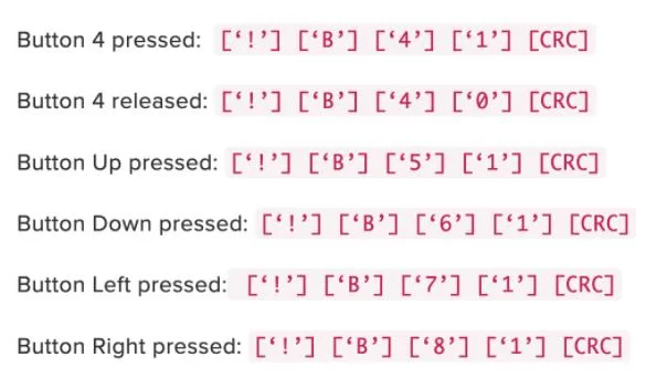
From the figure, one can see that each button press is prefixed by the characters “!B” followed by the button number, and a 0 for a release and 1 for a press. It should be noted that a string is sent by the bluetooth module once when a button is pressed, and another time when it is released. Therefore, by using a case statement on the first character of the string in the buffer, we can tell if we received a proper command. Once the case statement is entered, a function is called to handle the rest of the string to decide whether to toggle motor control pins to stop, turn, move backward, or forward. If a button is pressed, the robot will stay in the state resulting from that button press until a string is received telling the PIC32 that the button was released.
For the motor control, the software was responsible for interpreting the input from the user to the bluetooth module and move or shoot accordingly. There are five different inputs which the software had to decipher from the bluetooth module. For the four movement inputs, the software must set specific for the enable signal for the h-bridge. The four bits which control the motors are RB3, RB5, RB4, and RA3. Setting these bits to be either high or low, determine the direction which the motor will rotate. For example, to get the tank to move forward, RB3 and RB5 must be set to 0 (clear) and RA3 and RB4 must be set to 1 (set). This paired with sending a PWM signal from pins RB9 and RPA2, allows us to control how fast the tank moves. This is a crucial part, which is talked about in other sections because we needed to stop a certain distance away from an object without crashing and we needed to move in a straight line without veering one direction every time. In order to control the gun, it was much simpler since we used a relay. Since a relay acts as an electronic switch, we did not need a PWM signal to control the motors. This meant that when the software decoded a message from the bluetooth module to shoot, we would set RB14 to high, turning the gun motors on to shoot. When any button is released, the PWM signals are set to 0 and RB14 is set to low, ensuring that the robot stays stationary and does not shoot a dart until it receives a new signal. Additionally, the PWM signals for the tank motors were generated using two output compare peripherals on the PIC32 which were tied to Timer 2.p>
The ultrasonic sensor makes use of one GPIO pin (pin RA0 connected through the 3.3V to 5V logic level converter) and pin RA4 for the input capture module. According to the datasheet, in order to make the ultrasonic sensor actuate we need to pull the trigger pin high for at least 10us, which was done in a thread every 70ms. We created a software delay using the core timer which was partly taken from the tft source code. After this, the sensor will send back a stream of pulses, the width of which is proportional to the distance from the sensor in meters according to the following formula:
![]()
The input capture module was employed to read the width of each pulse. When pin RA4 detects either a rising or a falling edge, the input capture ISR will be triggered. We use a state machine to keep track of whether the ISR was triggered for a rising or a falling edge. If it is a rising edge, then we set the timer to 0. On the falling edge, we store the current timer value in a variable. The actual computation of the distance from the timer value is done in the ultrasonic sensor thread mentioned earlier. The input capture module relies on Timer 3, which was set up to count from 0 to 0xFFFF with a prescaler of 8 to ensure that the timer doesn’t overflow before we’ve hit a falling edge. Although we lose resolution by using a prescaler, it isn’t significant since the echo pulse width is on the order of milliseconds, while the clock period is on the order of hundreds of nanoseconds.
TESTING
We used an incremental testing approach through our entire design process. Before we implemented any piece of hardware, we made sure that each component worked as it was supposed to. For all of the motors, we ensured that when given the correct voltage and amps, they would spin. Once we verified that everything was in working order, we implemented one piece of hardware at a time with the PIC32.
The first piece of hardware we implemented was the h-bridge and motors. After verifying using the power supplies in the lab that the motors would spin given their supplied voltage, we began wiring them up to the h-bridge. Since in lab 3 we had already worked with controlling motors, we began modifying the code for the motor control in lab 3 to test out our motors. Once we got the motors able to be controlled by the PIC32, we then went about ensuring that we could control the direction of the motors by changing certain bits.
The second piece of hardware we implemented was the ultrasonic sensor. Once the supporting circuitry was implemented (logic level converter) and the sensor was connected to the correct pins, we first tried to visualize the echo pulse on the oscilloscope, and manually measured the pulse width at a well-defined distance away from an object. This was repeated for several distances before we integrated it with the motor control and the PIC32. Then, before putting the tank on the ground, we held it at a certain distance away from a wall and directed the motors to turn forward using the app. The button was held while we brought the tank closer to the wall at varying speeds to make sure that it stopped the motors at the correct distance. This was how we were able to find out that we needed to lower the max speed of the motors from what they were originally, as the tank would sometimes run into a wall before getting a new value from the ultrasonic sensor. If we received an issue such as the one where the motors continued to stall at an incorrect time (explained elsewhere in the report), we backtracked and hooked the sensor up to the big board so that we could diagnose the problem using the TFT.
After we implemented the ultrasonic sensor, we then implemented the gun. To implement the Nerf gun and allow for remote controlled firing, we need the use of an electrical relay switch. To test it, the first step was to ensure that with 3.3 volts applied to the switch, the switch would close, connecting the two wires. When the relay switch opens and closes, there is a subtle clicking noise from inside the relay that can be used to hear if the relay is opening and closing. Since the relay switch would open and close with 3.3 volts applied, the next step was to connect the relay to the PIC32 and try to hear for the opening and closing of the relay with the setting of a GPIO pin. However, when the relay switch was connected to an input pin of the PIC32, the relay would not open and close, even though each GPIO pin on the microcontroller outputs 3.3 volts. This is because when testing the relay switch first with the lab power supply, there was a greater current being applied across the relay. The PIC32 could not output as much current to open and close the relay, so it was necessary to increase the current sent to the relay. To do this, a circuit amplifier was designed to increase the current being sent to the relay. When both the circuit amplifier and the relay switch were connected to the PIC32 and a signal was sent to turn on the relay, a clicking noise was heard from the relay, indicating that the relay was, in fact, opening and closing. Lastly, with both the relay switch and circuit amplifier implemented, the last step was to connect the wires of the Nerf gun’s motors to the relay. With everything now wired up, with the press of a button on either a python GUI or the bluetooth’s app, the motors would spin as intended.
Before we implemented the bluetooth module, we ensured that we could control all of the hardware with a python gui with a tethered robot. This would ensure that everything was in working order as a whole, so that when we implemented the bluetooth module, if something isn’t working correctly, it was with respect to the bluetooth module and not that piece of hardware or software component. Lastly, we implemented the bluetooth module. Initially before trying things out with the control pad feature, we tried to first implement sending a simple string from a phone to the bluetooth module and have it show up on a TFT. Testing with this was done by pressing buttons on the app and observing the resulting behavior of the tank. When things worked incorrectly, we switched to using the big board so that we could print things out on the TFT which often gave us useful debugging information.
Additionally, since for the final product we used the smaller PIC32 development board, much of the testing of code for various components was done using the bigger PIC32 development board because of its inclusion of a TFT. For example, before connecting the bluetooth module control to the actual motors, we first made sure that the correct hex code sent from the phone app to the bluetooth module showed up on the TFT on a button press. We also ran into a bug where the motors would stall even though the ultrasonic sensor wasn’t close enough to another object to make the motors stop. We figured that the problem could originate from how the PIC32 was interacting with the ultrasonic sensor, so we hooked it up to the TFT and print out the distance measurement from it.
Since a large part of our project involved external hardware, we also used the oscilloscope as a major instrument for testing. The final circuit contained two 3.3V to 5V logic level converters, and to make sure that they were working properly before hooking it up to the PIC32, we used the DC power supply as well as the function generator as inputs and measured the output with the oscilloscope to make sure that the circuit was constructed correctly. Before hooking up the echo pin from the ultrasonic sensor to an input pin on the PIC32, we scoped the output and made sure that the pulse width grew as the distance of an object in front of it also grew.
RESULTS
For our final project, we were able to successfully design and build a remote control tank. Looking at the video below, you can see our tank in action. Anyone with a cell phone is able to download the Adafruit Bluefruit app on the Appstore or Google Play Store and will be able to use the app to control our remote control tank. When using the app, make sure to hold the buttons to control the tank and not tap, or the tank will be stuck doing which button you pressed. This happens because the tank receives the signal, but since it is too quick, the tank never receives the stop signal. As you can see in the video, our robot is able to move in all directions and turn around. Additionally, it is able to stop carefully in front of objects and maneuver away from objects easily. In order for our tank to be safe and not harm people or cause major damage, the nerf gun fires forward, only allowing it to hit objects at ankle level. Another aspect we had to figure out was how fast the robot needed to move in order for the robot to stop when it became too close to an object. This was done by fine tuning the PWM signals we sent to the motors, which we found to be 35000. In addition, we also needed to calibrate the motors, since two motors that are the exact same may not behave the same. However, we did find through testing the motors that they were similar enough that when the tank moves forward, giving both motors the same PWM duty cycle, the robot wouldn’t veer off in one direction.
CONCLUSIONS
GENERAL REFLECTIONS
From our first project design to our final outcome, we were able to create a remote control tank as we set out to do. We learned a lot about the engineering design process and how to turn our ideas into a reality. This project taught us that nothing is as simple as you might think, issues always arise and overcoming these challenges can be more exciting than the final outcome. Working in a group is extremely beneficial, allowing for tasks to be split up and completed more efficiently, but also gives you another perspective on something you may be struggling with.
ISSUES FACED
The biggest issue we faced was with the first bluetooth module we were trying to implement. The first bluetooth module we were trying to implement would communicate with the PIC32 via SPI. (bytes). The next issue we faced with this module was that we were able to connect to it via bluetooth with our phone or laptop, but we were unable to send or receive information from the PIC32. We were able to fix this issue by ordering the same module, but instead of communicating with SPI, it communicated with UART. We switched from using the SDEP protocol that adafruit had defined in their datasheet in conjunction with SPI to sending strings using the PIC32 UART1 channel and DMA.
Another issue that took a while to resolve involved the ultrasonic sensor. The initial problem, as mentioned earlier, stemmed from the motors stalling even though the ultrasonic sensor wasn’t within the range of distances to stop. We slightly changed the current implementation of the code so that the values of the ultrasonic sensor could be transmitted over bluetooth to the phone app. We observed the ultrasonic sensor distance measurements as an object was brought farther and farther away from it. What we observed was that the measurement would increase (as expected), but at regular intervals would reset to 0 and continue increasing. This suggested that the timer which the input capture module was connected to was overflowing because the echo pulse which we were measuring with the input capture module was wider than the counter could count up to. To fix this, we increased the prescaler of the timer. By doing this we compromised a bit on resolution of the distance measurement, but the timer period still remained short in relation to the echo pulse width, so the effects were not as pronounced.
INTELLECTUAL, ETHICAL, AND SAFETY CONSIDERATIONS
For our final project we utilized the Adafruit Bluefruit LE UART Friend code provided on the course website in order to use the bluetooth module. Additionally, we had to abide by the IEEE 802.15 standard for bluetooth communication and used frequencies in the range of 2.402 GHz to 2.48 GHz. Lastly, since we were working with a projectile, we had to ensure the safety of everyone in the lab and equipment at all times. This meant we never left our tank loaded unless we were testing and that we had something to block the bullet so it wouldn’t shoot someone or something.
FURTHER IMPROVEMENTS
In order to improve upon the firing capabilities of the tank, we would want to implement the ability to reload a Nerf dart automatically. When taking apart the Nerf gun for the first time, we became aware of the fact that each dart is loaded with each press of the trigger mechanism. For us to implement this into our design and make it automatic, we would need to include a linear actuator to move the next dart into position. Our implementation involved placing the dart into a tray right behind the motors, so when the motors would spin, the dart would catch the motors and shoot. This had to be done manually after each launch as there could only be one dart in the tray at a time. The tray part of the mechanism could stay the same as it was designed to be the right distance to allow the dart to catch onto the motors, but to implement automatic reloading, a linear actuator could be installed to drop the next dart into position after each consecutive launch.
Another implementation we could improve upon in the shooting angle. In our design and budget, we did not have the ability to implement a motor that could raise or lower the angle of the Nerf gun, so our robot could only shoot straight forward. Adding a motor that could raise the angle of the Nerf gun would give us the ability to adjust the distance the Nerf dart goes and allow for more accurate distance shots. With this improvement, we would have to be careful with shooting because we could cause harm to someone if they were shot in the eye or damage to something in the lab.
Furthermore, using another bluetooth module that isn’t as proprietary might allow us to expand the functionality and customizability of the tank. Our initial plan was to create a python GUI that connected to a bluetooth module from a script running on a laptop, but the library supplied by adafruit was full of bugs, and our laptops weren’t able to detect the bluetooth advertisement of the module without using the app to connect to it. Using another bluetooth module would allow us to manipulate and visualize data in more interesting ways.
APPENDIX: A
“The group approves this report for inclusion on the course website.”
“The group approves the video for inclusion on the course youtube channel.”
APPENDIX: CODE
/*
* File: tank.c
* Author: lmm343, mah426, chk57
*
* Created on November 4, 2021, 2:57 PM
*/
#include
#include “config_1_3_3.h”
// threading library
#include “pt_cornell_1_3_3.h”
// For below libraries comment out when transferring to other board
////////////////////////////////////
// graphics libraries
// SPI channel 1 connections to TFT
// #include “tft_master.h”
// #include “tft_gfx.h”
// need for rand function
#include
// need for sine function
#include
// The fixed point types
#include
////////////////////////////////////
// Speed of sound in m/s
#define SPEED_OF_SOUND 340.0
/* US Use note
* travel distance of ultrasonic wave = (speed of sound) x (echo pulse duration)
* distance from sensor to object = (travel_distance)/2
*
* Can trigger a timer using input compare module on the detect of a rising edge
* stop timer on falling edge –> gets duration of on timer for pulse
*/
#define PBCLK 40000000 // peripheral bus clock
#define del_us PBCLK/2000000
int generate_period = 40000;
volatile int pwm_on_time1 = 35000;
volatile int pwm_on_time2 = 35000;
volatile int move = 0;
volatile int back = 0;
volatile float duration;
volatile float dist;
float last_dist = 0;
//The measured period of the wave
volatile unsigned int t=0, t_prev=0, pulse_width=0;
volatile int rising = 1;
// Software delay of i microseconds
void delay_micro(unsigned long i){
unsigned int j;
j = del_us * i;
WriteCoreTimer(0);
while (ReadCoreTimer() < j);
}
//==========================Timer for 1kHz sample rate==========================
void __ISR(_TIMER_2_VECTOR, ipl2) Timer2Handler(void)
{
mT2ClearIntFlag();
if ( dist > 15 && move == 1 ) { //dist > 5 &&
SetDCOC3PWM(pwm_on_time1);
SetDCOC4PWM(pwm_on_time2);
} else if (move == 1 && back == 1) {
SetDCOC3PWM(pwm_on_time1);
SetDCOC4PWM(pwm_on_time2);
} else {
SetDCOC3PWM(0);
SetDCOC4PWM(0);
}
}
volatile int debounce = 0;
// == Capture 1 ISR ====================================================
// check every cpature for consistency
void __ISR(_INPUT_CAPTURE_1_VECTOR, ipl3) C1Handler(void)
{
// read the capture register
t = mIC1ReadCapture();
if (rising == 0) {
// compute the repeating interval
pulse_width = t;
// duration = (float)pulse_width*(1.0/40000000.0);
// dist = ((SPEED_OF_SOUND*duration))*50;
rising = 1;
}else {
WriteTimer3(0x0);
t_prev = 0;
rising = 0;
}
// clear the timer interrupt flag
mIC1ClearIntFlag();
}
// === print a line on TFT =====================================================
// Utilities to print a line on the TFT
// Predefined colors definitions (from tft_master.h)
//#define ILI9340_BLACK 0x0000
//#define ILI9340_BLUE 0x001F
//#define ILI9340_RED 0xF800
//#define ILI9340_GREEN 0x07E0
//#define ILI9340_CYAN 0x07FF
//#define ILI9340_MAGENTA 0xF81F
//#define ILI9340_YELLOW 0xFFE0
//#define ILI9340_WHITE 0xFFFF
// string buffer
//char buffer[60];
//void printLine(int line_number, char* print_buffer, short text_color, short back_color){
// // line number 0 to 31
// /// !!! assumes tft_setRotation(0);
// // print_buffer is the string to print
// int v_pos;
// v_pos = line_number * 10 ;
// // erase the pixels
// tft_fillRoundRect(0, v_pos, 239, 8, 1, back_color);// x,y,w,h,radius,color
// tft_setTextColor(text_color);
// tft_setCursor(0, v_pos);
// tft_setTextSize(1);
// tft_writeString(print_buffer);
//}
void move_robot(char* cmd) {
char buffer[30];
if (cmd[2] == ‘5’ && cmd[3] == ‘1’) { // move the robot forward
// tft_fillRoundRect(0,0, 120, 50, 1, ILI9340_BLACK);// x,y,w,h,radius,color
// tft_setTextColor(ILI9340_WHITE);
// tft_setCursor(5, 20);
// tft_setTextSize(1);
// tft_writeString(buffer);
// sprintf(buffer, “forward”);
pwm_on_time1 = 35000;
pwm_on_time2 = 35000;
// if (dist > 10){
mPORTBClearBits(BIT_3);
mPORTBClearBits(BIT_5);
mPORTASetBits(BIT_3);
mPORTBSetBits(BIT_4);
// } else {
// mPORTBClearBits(BIT_3);
// mPORTBClearBits(BIT_5);
// mPORTAClearBits(BIT_3);
// mPORTBClearBits(BIT_4);
// }
move = 1;
back = 0;
} else if (cmd[2] == ‘6’ && cmd[3] == ‘1’) { // move the robot back
// tft_fillRoundRect(0,0, 120, 50, 1, ILI9340_BLACK);// x,y,w,h,radius,color
// tft_setTextColor(ILI9340_WHITE);
// tft_setCursor(5, 20);
// tft_setTextSize(1);
// tft_writeString(buffer);
// sprintf(buffer, “back”);
pwm_on_time1 = 35000;
pwm_on_time2 = 35000;
mPORTBSetBits(BIT_3);
mPORTBSetBits(BIT_5);
mPORTAClearBits(BIT_3);
mPORTBClearBits(BIT_4);
move = 1;
back = 1;
} else if (cmd[2] == ‘7’ && cmd[3] == ‘1’) { // move the robot left
// tft_fillRoundRect(0,0, 120, 50, 1, ILI9340_BLACK);// x,y,w,h,radius,color
// tft_setTextColor(ILI9340_WHITE);
// tft_setCursor(5, 20);
// tft_setTextSize(1);
// tft_writeString(buffer);
// sprintf(buffer, “left”);
pwm_on_time1 = 35000;
pwm_on_time2 = 35000;
mPORTBSetBits(BIT_3);
mPORTBClearBits(BIT_5);
mPORTAClearBits(BIT_3);
mPORTBSetBits(BIT_4);
move = 1;
back = 0;
} else if (cmd[2] == ‘8’ && cmd[3] == ‘1’) { // move the robot right
// tft_fillRoundRect(0,0, 120, 50, 1, ILI9340_BLACK);// x,y,w,h,radius,color
// tft_setTextColor(ILI9340_WHITE);
// tft_setCursor(5, 20);
// tft_setTextSize(1);
// tft_writeString(buffer);
// sprintf(buffer, “right”);
pwm_on_time1 = 35000;
pwm_on_time2 = 35000;
mPORTBClearBits(BIT_3);
mPORTBSetBits(BIT_5);
mPORTASetBits(BIT_3);
mPORTBClearBits(BIT_4);
move = 1;
back = 0;
} else if (cmd[2] == ‘1’ && cmd[3] == ‘1’) {
// tft_fillRoundRect(0,0, 120, 50, 1, ILI9340_BLACK);// x,y,w,h,radius,color
// tft_setTextColor(ILI9340_WHITE);
// tft_setCursor(5, 20);
// tft_setTextSize(1);
// tft_writeString(buffer);
// sprintf(buffer, “shoot”);
mPORTBSetBits(BIT_14);
move = 0;
back = 0;
} else if (cmd[3] == ‘0’) { // stop the robot if button 1 was pressed
// tft_fillRoundRect(0,0, 120, 50, 1, ILI9340_BLACK);// x,y,w,h,radius,color
// tft_setTextColor(ILI9340_WHITE);
// tft_setCursor(5, 20);
// tft_setTextSize(1);
// tft_writeString(buffer);
// sprintf(buffer, “stop”);
move = 0;
back = 0;
mPORTBClearBits(BIT_14);
}
}
//=== Serial terminal thread =================================================
// simple command interpreter and serial display
// BUT NOTE that there are TWO completely different modes of getting strings
// from the UART. ONe assumes a human is typing, the other assumes a machine
//
// Also — AUX uart loopback transmit thread using the ‘s’ command
// semaphores to sync threads
int ready_to_send=1, ready_to_receive=0 ;
// NOTE that command ‘s’ below sends/receives data via the
// UART1 AUX machine communcation channel.
// mode==1 is command mode; 2 is data mode
static int mode = 1;
static PT_THREAD (protothread_serial(struct pt *pt))
{
PT_BEGIN(pt);
static char cmd[30], t0;
static char prev_cmd[30];
static float value;
static int i;
static int go = 0;
static int v1, v2;
static char buffer[30];
// string recognized by module to toggle data<->command
static char cmd_data_toggle[] = “+++\r”;
// termination for machine buffer
PT_terminate_char = ‘#’ ; // see http://www.asciitable.com/
PT_terminate_count = 0 ;
// time in milliseconds!
PT_terminate_time = 0 ;
// semaphores for sync two thread
while(1) {
// get config or move cmd from bt module
PT_SPAWN(pt, &pt_DMA_input_aux, PT_GetMachineBuffer_aux(&pt_DMA_input_aux) );
sscanf(PT_term_buffer_aux, “%s %f”, cmd, &value);
// ==============================================
// At this point, we have a valid string buffer
// Now parse it:
// === command parser ================================
switch(cmd[0]) {
case ‘m’:
// toggle the bluetooth module mode between ‘command’ and ‘data’
// mode==1 is command mode
if (mode == 1) mode=2; // go to data mode
else mode = 1; // goto command mode
// now send the mode change to the module
strcpy(PT_send_buffer_aux, cmd_data_toggle);
PT_YIELD_UNTIL(pt, ready_to_send==1);
ready_to_receive = 1;
ready_to_send = 0 ;
PT_YIELD(pt);
PT_SPAWN(pt, &pt_DMA_output_aux, PT_DMA_PutSerialBuffer_aux(&pt_DMA_output_aux) );
break;
case ‘s’:
// read a string into the aux send buffer
// IN COMMAND MODE:
// — returns bluetooth module response
// IN DATA MODE:
// — returns string from remote bluetooth device
// — hangs until it gets a response with ‘\r’ terminator
//
// get the string (command or payload data) to send to the module
sscanf(PT_term_buffer_aux, “%s %s”, cmd, PT_send_buffer_aux);
strcat(PT_send_buffer_aux, “\r”);
//
//send a string to bluetooth module thru UART1 (AUX))
// wait for the read to be done
PT_YIELD_UNTIL(pt, ready_to_send==1);
// start the read, THEN start the write
// signal the receive thread that data is coming
ready_to_receive = 1;
// clear the ready flag until read thread is done
ready_to_send = 0 ;
// wait a little so that receive thread is ready
// and the DMA channel is ready
PT_YIELD(pt);
// send using AUX USART
// NOTE: set as ending character (of a string) in PT_DMA_PutSerialBuffer_aux
// REQUIRED by ADAFRUIT SERIAL FRIEND
// setting the end character to NULL transmits the NULL,
// which confuses the module
PT_SPAWN(pt, &pt_DMA_output_aux, PT_DMA_PutSerialBuffer_aux(&pt_DMA_output_aux) );
// wait for the AUX receive to actually happen
// (see receive thread))
// (including time outs)
PT_YIELD_UNTIL(pt, ready_to_send==1);
break;
case ‘!’: // Signals that a button from the control pad was pressed
go = 1;
move_robot(cmd);
// case ‘g’:
// go = 0;
// if (go == 0) {
// sprintf(buffer, “%f”, dist);
// sprintf(buffer, “%f , %d”, dist, pulse_width);
//
// strcpy(PT_send_buffer_aux, buffer);
//
// strcat(PT_send_buffer_aux, “\r”);
// //
// //send a string to bluetooth module thru UART1 (AUX))
// // wait for the read to be done
// PT_YIELD_UNTIL(pt, ready_to_send==1);
// // start the read, THEN start the write
// // signal the receive thread that data is coming
// ready_to_receive = 1;
// // clear the ready flag until read thread is done
// ready_to_send = 0 ;
// // wait a little so that receive thread is ready
// // and the DMA channel is ready
// PT_YIELD(pt);
//
// // send using AUX USART
// // NOTE: set as ending character (of a string) in PT_DMA_PutSerialBuffer_aux
// // REQUIRED by ADAFRUIT SERIAL FRIEND
// // setting the end character to NULL transmits the NULL,
// // which confuses the module
// PT_SPAWN(pt, &pt_DMA_output_aux, PT_DMA_PutSerialBuffer_aux(&pt_DMA_output_aux) );
//
// // wait for the AUX receive to actually happen
// // (see receive thread))
// // (including time outs)
// PT_YIELD_UNTIL(pt, ready_to_send==1);
//
// }
//
// case ‘f’:
// go == 1;
//
//
} // end switch statement
// never exit while
} // END WHILE(1)
PT_END(pt);
} // thread serial
// ========================================================
// AUX uart receive thread
static PT_THREAD (protothread_serial_aux(struct pt *pt))
{
PT_BEGIN(pt);
// termination for machine buffer on AUX channel
// terminate on ‘#’ OR 6 caracters OR 1000 mSec
// whichever comes first
PT_terminate_char_aux = 0 ; // see http://www.asciitable.com/
PT_terminate_count_aux = max_chars_aux ;
// time in milliseconds!
PT_terminate_time_aux = 500 ;
while(1) {
if (mode==1) { // command mode. No required, so can receive multiple lines
PT_terminate_char_aux = 0 ; // allow multiple line receive
PT_terminate_count_aux = max_chars_aux ;
// time in milliseconds!
PT_terminate_time_aux = 500 ;
// wait for data transmission start
}
else { // data mode terminated by , no time limit
PT_terminate_char_aux = ‘\r’ ; // see http://www.asciitable.com/
PT_terminate_count_aux = max_chars_aux ;
// time in milliseconds!
PT_terminate_time_aux = 0 ; // no time out for radio respose
}
PT_YIELD_UNTIL(pt, ready_to_receive==1);
ready_to_receive = 0 ;
// get sent data on AUX channel (UART1 loopback)
PT_SPAWN(pt, &pt_DMA_input_aux, PT_GetMachineBuffer_aux(&pt_DMA_input_aux) );
// reset semaphore to indicate data received
// (or timed out)
ready_to_send = 1;
// NEVER exit while
} // END WHILE(1)
PT_END(pt);
} // aux uart thread
/*
* IN1 –> RPB3
* IN2 –> RPA3
* IN3 –> RPB4
* IN4 –> RPB6
*/
int num = 0;
static PT_THREAD (protothread_us(struct pt *pt)) {
PT_BEGIN(pt);
static char buffer[128];
static float new_dist;
while(1) {
PT_YIELD_TIME_msec(70);
mPORTASetBits(BIT_0);
delay_micro(10);
mPORTAClearBits(BIT_0);
duration = (float)pulse_width*(1.0/5000000.0);
dist = ((SPEED_OF_SOUND*duration))*50;
// tft_fillRoundRect(0,0, 120, 50, 1, ILI9340_BLACK);// x,y,w,h,radius,color
// tft_setTextColor(ILI9340_WHITE);
// tft_setCursor(5, 20);
// tft_setTextSize(1);
// tft_writeString(buffer);
// sprintf(buffer,”dist=%f “, dist);
}
PT_END(pt);
}
/*
*
*/
void main(void) {
ANSELA = 0; ANSELB = 0;
PT_setup();
// timer interrupt //////////////////////////
// Set up timer3 on, interrupts, internal clock, prescalar 1, toggle rate
// at 40 MHz PB clock +
// 40,000,000/1000 = 40000 : since timer is zero-based, set to 39999
OpenTimer2(T2_ON | T2_SOURCE_INT | T2_PS_1_1, 39999);
// set up the timer interrupt with a priority of 2
ConfigIntTimer2(T2_INT_ON | T2_INT_PRIOR_2);
mT2ClearIntFlag(); // and clear the interrupt flag
// timer interrupt //////////////////////////
// Set up timer3 on, interrupts, internal clock, prescalar 1, toggle rate
// at 40 MHz PB clock
// Triggers every 100us
// 5,000,000/1000 = 5000 : since timer is zero-based, set to 3999
OpenTimer3(T3_ON | T3_SOURCE_INT | T3_PS_1_8, 0xFFFF);
mT3ClearIntFlag(); // and clear the interrupt flag
// set up compare3 for double compare mode
// first number is the time to clear, second is the time to set the pin
// in this case, the end of the timer period and 50% of the timer period
OpenOC3(OC_ON | OC_TIMER2_SRC | OC_PWM_FAULT_PIN_DISABLE, generate_period-1, generate_period>>1); //
// OC3 is PPS group 4, map to RPB9 (pin 18)
PPSOutput(4, RPB9, OC3);
// set up compare3 for double compare mode
// first number is the time to clear, second is the time to set the pin
// in this case, the end of the timer period and 50% of the timer period
OpenOC4(OC_ON | OC_TIMER2_SRC | OC_PWM_FAULT_PIN_DISABLE, generate_period-1, generate_period>>1); //
// OC3 is PPS group 4, map to RPB9 (pin 18)
PPSOutput(3, RPA2, OC4);
// set up input compare module
OpenCapture1( IC_EVERY_EDGE | IC_INT_1CAPTURE | IC_TIMER3_SRC | IC_ON );
ConfigIntCapture1(IC_INT_ON | IC_INT_PRIOR_3 | IC_INT_SUB_PRIOR_3 );
INTClearFlag(INT_IC1);
// connect PIN 24 to IC3 capture unit
PPSInput(3, IC1, RPA4);
mPORTBSetPinsDigitalOut(BIT_3 | BIT_5 | BIT_4 | BIT_14); // BIT_14 is for gun
mPORTASetPinsDigitalOut(BIT_3 | BIT_0); // BIT_0 is for the US sensor
mPORTAClearBits(BIT_3 | BIT_0);
mPORTBClearBits(BIT_10 | BIT_14 | BIT_5 | BIT_3 | BIT_4);
// // init the display
// // NOTE that this init assumes SPI channel 1 connections
// tft_init_hw();
// tft_begin();
// tft_fillScreen(ILI9340_BLACK);
// //240×320 vertical display
// tft_setRotation(0); // Use tft_setRotation(1) for 320×240
// === setup system wide interrupts ========
INTEnableSystemMultiVectoredInt();
// === identify the threads to the scheduler =====
// add the thread function pointers to be scheduled
// — Two parameters: function_name and rate. —
// rate=0 fastest, rate=1 half, rate=2 quarter, rate=3 eighth, rate=4 sixteenth,
// rate=5 or greater DISABLE thread!
pt_add(protothread_us, 0);
pt_add(protothread_serial, 1);
pt_add(protothread_serial_aux, 0);
// === initalize the scheduler ====================
PT_INIT(&pt_sched);
// >>> CHOOSE the scheduler method: <<<
// (1)
// SCHED_ROUND_ROBIN just cycles thru all defined threads
//pt_sched_method = SCHED_ROUND_ROBIN ;
// NOTE the controller must run in SCHED_ROUND_ROBIN mode
// ALSO note that the scheduler is modified to cpy a char
// from uart1 to uart2 for the controller
pt_sched_method = SCHED_ROUND_ROBIN;
// === scheduler thread =======================
// scheduler never exits
PT_SCHEDULE(protothread_sched(&pt_sched));
// ============================================
}