Summary of Digital Clock using PIC Microcontroller and DS1307 RTC
Summary (under 100 words): This article describes building a digital clock using a PIC microcontroller, DS1307 RTC, and a 16×2 LCD. The DS1307 supports 12/24-hour modes, AM/PM, automatic month-length and leap-year adjustment up to 2100, and battery-backed power switching. Communication uses I2C. The author notes BCD-format handling for DS1307, converting between BCD and binary for arithmetic, and converting numeric data to characters for the LCD. Proteus simulation may require an I2C Debugger. MikroC source code and Proteus files are provided.
Parts used in the Digital Clock:
- PIC Microcontroller
- DS1307 Real Time Clock (RTC)
- 16×2 LCD display
- 3V CMOS backup battery
- I2C bus connections (SCL and SDA)
- Power supply: +5V (VDD/VCC) and 0V (VSS/GND)
- Proteus I2C Debugger (for simulation)
- Development tools: MikroC source code and Proteus project files
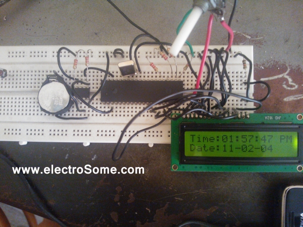
A Digital Clock can be made easily by using PIC Microcontroller, DS1307 and a 16×2 LCD. I have already posted about Interfacing DS1307 RTC with PIC Microcontroller. The DS1307 RTC can work either in 24-hour mode or 12-hour mode with AM/PM indicator. It automatically adjusts for months fewer than 31 days including leap year compensation up to year 2100. DS1307 comes with built-in power sensing circuit which senses power failures and automatically switches to back up supply. We can provide a 3V CMOS Battery for that. Communication between PIC Microcontroller and DS1307 takes place through I²C Bus.
 Suggested Readings:
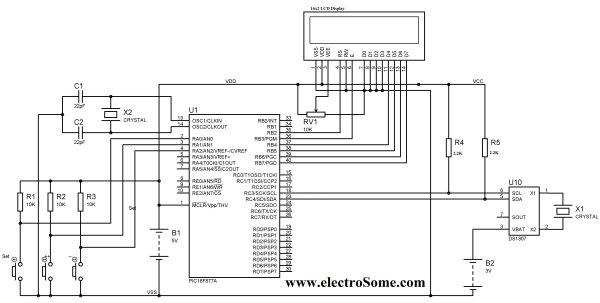
Circuit Diagram – Digital Clock
Note: VDD , VSS of the Pic Microcontroller and VCC , GND of DS1307 are not shown in the circuit diagram. VDD, VCC should be connected to +5V and VSS, GND to OV as marked in the circuit diagram.
To simulate this project in Proteus you may need to connect I2C Debugger. SCL and SDA of I2C Debugger should be connected in parallel to SCL and SDA of DS1307. I2C Debugger can be found where CRO can be found in Proteus.
You can download the MikroC Source Code and Proteus Files etc at the end of this article. Here I explains the Source Code and different functions used in it.
 The Three points to be noted while editing or creating program for this project:
- DS1307 RTC is fully Binary Coded Decimal (BCD) clock/calender. So the data read from DS1307 should be converted to required format according to our needs and data to be written to DS1307 should be in BCD format.
- Library for Interfacing LCD With PIC Microcontroller of MikroC needs Character or String Data. So data to be displayed in the LCD Screen should be converted to Character.
- Addition and Subtraction cannot be directly applied on BCD. Here I first convert BCD to Binary. Then addition and subtraction can be simply applied on Binary. Then the Binary is converted back to BCD.
For more detail: Digital Clock using PIC Microcontroller and DS1307 RTC
- How does the PIC communicate with the DS1307?
Communication between the PIC Microcontroller and DS1307 takes place through the I2C Bus. - Can the DS1307 operate in 12-hour format with AM/PM?
Yes, the DS1307 can work either in 24-hour mode or 12-hour mode with AM/PM indicator. - Does the DS1307 handle month lengths and leap years?
Yes, it automatically adjusts for months fewer than 31 days including leap year compensation up to year 2100. - What backup power does the DS1307 use during power failure?
DS1307 has a built-in power sensing circuit and can switch to a 3V CMOS backup battery. - How should data be formatted when writing to or reading from DS1307?
DS1307 uses Binary Coded Decimal (BCD), so data read must be converted from BCD and data written must be in BCD format. - Why convert BCD to binary in the program?
Addition and subtraction cannot be directly applied on BCD, so BCD is converted to binary for arithmetic, then converted back to BCD. - What format does the LCD library in MikroC expect?
The MikroC LCD library needs character or string data, so numeric data must be converted to characters for display. - Do I need any special component to simulate the project in Proteus?
To simulate the project in Proteus you may need to connect the I2C Debugger with SCL and SDA connected to DS1307.