Summary of Digital Thermometer using PIC16F877A and LM35
This project reads temperature from an LM35 analog sensor with a PIC16F877A microcontroller and displays the temperature on six multiplexed common-cathode seven-segment displays. The PIC ADC converts the LM35 output to digital, the code formats digits and uses timer-driven interrupt multiplexing to refresh each 7-seg. digit. The displayed value is computed from the LM35 voltage (10 mV per °C) and mapped to segment masks in software.
Parts used in the Digital Thermometer:
- LM35 temperature sensor
- PIC16F877A microcontroller
- Six common-cathode 7-segment displays
- Resistors (for segment current limiting and pull-ups as required)
- Connecting wires and breadboard or PCB
- Power supply (Vcc and GND for PIC and LM35)
- Crystal or oscillator for PIC if required (per PIC setup)
- Proteus simulation files (optional, for virtual testing)
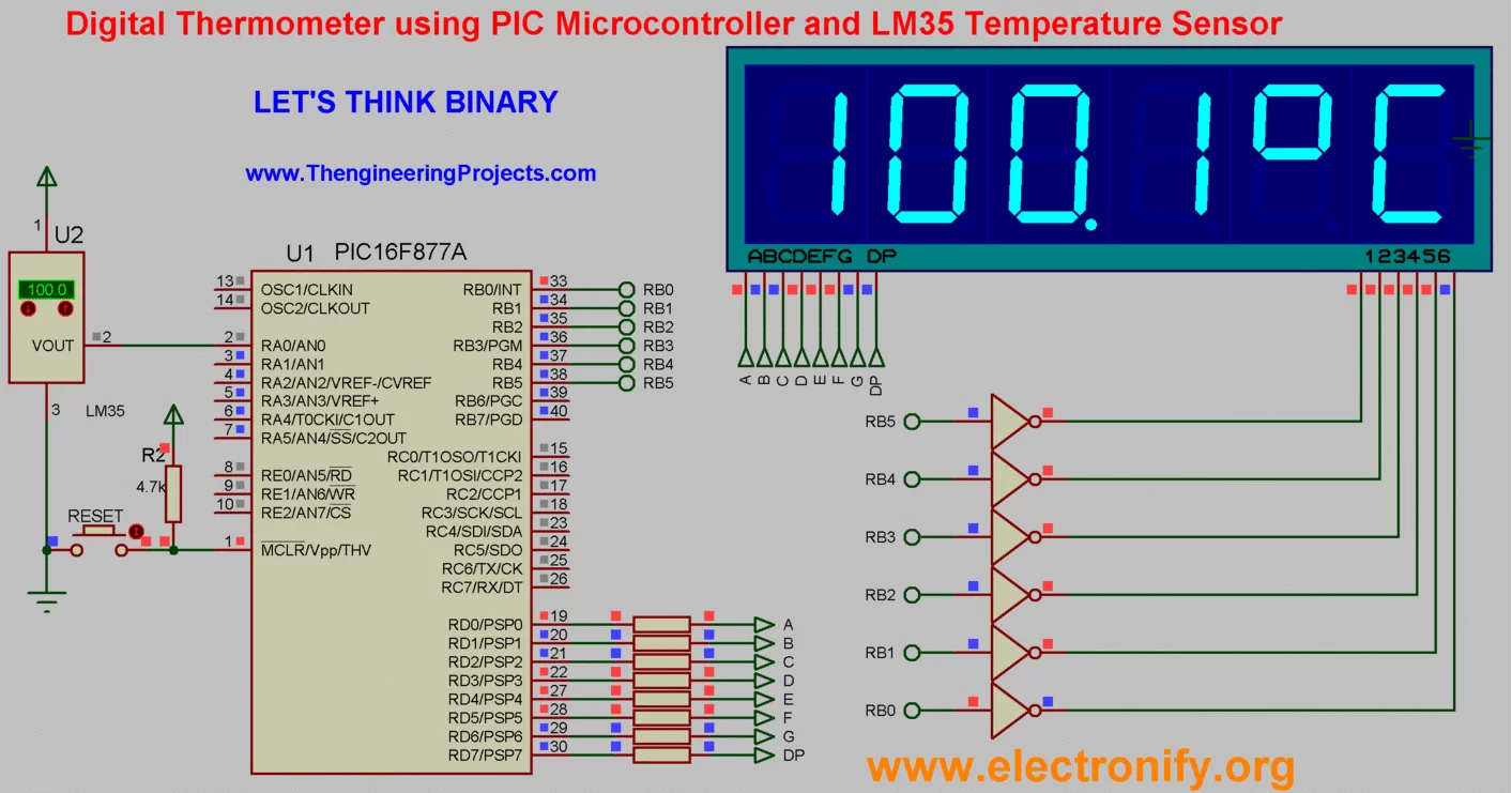
This is a simple project showing you how to read LM35 analog temperature sensor using a PIC
microcontroller and six seven segment (common cathod).In this tutorial we will make a practical use of multiplexed seven segment displays. We will use them to show current temperature usinga LM35 temperature sensor.
The temperature sensors are connected to the ADC ports of the microcontroller, which takes in the analog signal and gives out digital values across specified ports.
Across the defined output port of the microcontroller, seven segments are connected with takes the values of the temperature sensor and displays it
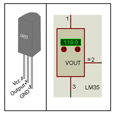
LM35 Temperature Sensor :
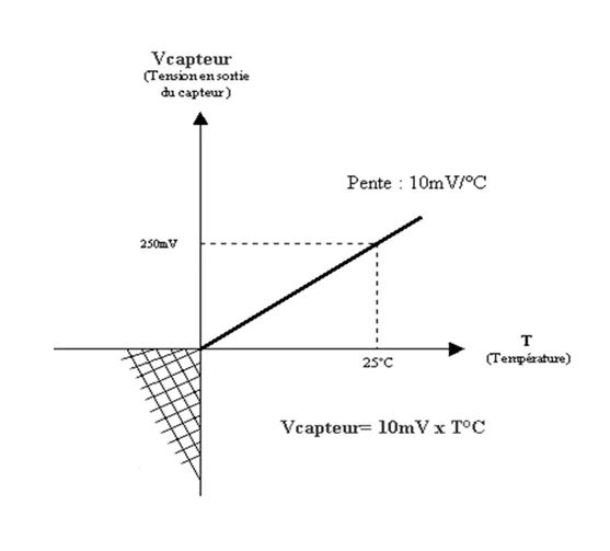
LM35 is a Three-Pins (Vcc,Output,GND) high precision temperature sensor having a resolution of 10mV/C starting at 0V (i.e. an output of 0V represents a temperature of 0C).
So :
10mV —> 1C
20mV —> 2C
500mV —> 50C and so on
PIC16F877A microcontroller built in ADC (analog to digital converter) isused to measure analog voltage. The analog to digital conversion is done by the PIC ADC module. In the code, I’ve used the mikro C library function for ADC. You can view the library file here: http://www.mikroe.com/download/eng/documents/compilers/mikroc/pro/pic/help/adc_library.htm
Digital Thermometer using PIC16F877A and LM35 (Code)
//Project: A Digital Temperature meter using an LM35 and PIC16F877A

//-------------- Returns mask for common cathode 7-seg. display

unsigned short num;

unsigned short mask(unsigned short num)

{

switch (num)

{

case 0 : return 0x3F;

case 1 : return 0x06;

case 2 : return 0x5B;

case 3 : return 0x4F;

case 4 : return 0x66;

case 5 : return 0x6D;

case 6 : return 0x7D;

case 7 : return 0x07;

case 8 : return 0x7F;

case 9 : return 0x6F;

} //case end

}

char val;

unsigned short shifter, j, portd_index;

unsigned int i;

unsigned short portd_array[6];

float teminc,temp;

void interrupt() {

PORTB = 0;

PORTD = portd_array[portd_index];

PORTB = shifter;              // turn on appropriate 7seg. display

shifter <<= 1; if (shifter > 32u)

shifter = 1;                // prepare mask for digit

portd_index++ ;

if (portd_index > 5u)

portd_index = 0;                 // turn on 1st, turn off 2nd 7seg.

TMR0   =   0;

INTCON = 0x20;

}//~

void main() {

OPTION_REG = 0x80;

j          =   0;

portd_index          =   0;

shifter         =   1;

TMR0       =   0;

INTCON     = 0xA0;       // Disable PEIE,INTE,RBIE,T0IE

ADCON1 = 0x80;

CMCON      = 0X07;       //DISABLE COMPARATORS

PORTA      =   0;

TRISA      =   0x01;

PORTD      =   0;

TRISD      =   0;

PORTB      =   0;

TRISB      =   0;

i          =   0;

do {

temp = ADC_Read(0);        // Read signal from LM35

temp = temp*5.0/1023.0;

teminc = temp*1000.0;     //Convert to  Temperature

i= teminC;

j = i / 1000u ;        // prepare digits for diplays

val = mask(j);

portd_array[5] = val;

j = (char)(i / 100u) % 10u;

val = mask(j);

portd_array[4] = val;

j = (char)((i / 10u) % 10u);

val = (mask(j)|0x80);

portd_array[3] = val;

j = i % 10u;

val = mask(j);

portd_array[2] = val;

portd_array[1] = 0x63;

portd_array[0] = 0x39;

Delay_ms(1000);

} while(1);              // endless loop

}//~
Digital Thermometer using PIC16F877A and LM35 (Schematic Diagram)
Demonstration :
DownloadHere
You can download the MikroC Source Code and Proteus files etc from here :
http://adf.ly/1d3tpP
This Our Group (thanks to join and participate) : https://www.facebook.com/groups/816450708460518/
Facebook page : https://www.facebook.com/Lets-Think-Binary-1728910547340654/
- How is temperature measured in this project?
Temperature is measured by the LM35 which outputs 10 mV per degree Celsius and is read by the PIC16F877A ADC. - Can the PIC16F877A read the LM35 output directly?
Yes, the PIC16F877A built-in ADC reads the LM35 analog output directly. - How are six seven-segment displays driven?
They are multiplexed: PORTD holds segment patterns and PORTB selects the active digit in a timer-driven interrupt routine. - What conversion is used to get temperature from ADC reading?
The ADC reading is converted to voltage using temp = ADC_Read(0)*5.0/1023.0, then to millivolts and temperature since 10 mV corresponds to 1 C. - Does the project use common anode or common cathode displays?
The project uses common-cathode seven-segment displays. - What microcontroller ports are used for display and ADC?
Seven-segment patterns are output on PORTD and digit selection is on PORTB; ADC input is read from AN0 (PORTA pin 0) in the code. - Is there sample code available for this project?
Yes, MikroC source code is provided in the article, including mask function, ADC read and multiplexing interrupt. - How often are display digits updated?
The code uses a timer interrupt to cycle digits rapidly and Delay_ms(1000) in the main loop for reading/updating values once per second.