Summary of Arduino controlled Dual Mono AK4490 DAC (Part 3)
This article details a fully discrete single-ended Class-A output stage designed by Kostas, featuring an AK4490 DAC and ~2.4V RMS output. It covers the Bill of Materials (BoM), sourcing specific components like UPA68H transistors from eBay, and matching requirements for T8/T9 pairs within 5%. The guide explains power supply needs (ideally +/-16VDC), bias adjustment procedures using trimmers R26A/B to achieve ~25mA per rail, and final DC offset checks. Design notes mention inverting architecture and optional DSD filter relays.
Parts used in the AK4490 Discrete Output Stage:
- AK4490 dual mono DAC
- UPA68H transistors
- T8A and T9A transistors
- T8B and T9B transistors
- Multi-turn trimmers R26A and R26B
- Relay for filter switching
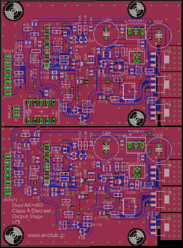
This output stage is the brainchild of my friend Kostas, all I did was lay out the PCB.
It is a fully discreet single-ended class-A output stage, outputting ~2.4V RMS.
And this is the BoM: AK4490 dual mono DAC – Discreet Analog stage BOM (371 downloads)
The BoM includes part numbers for most parts from Mouser. The only parts that are not in production and must be found elsewhere are the UPA68H. Ebay is a good bet. Chances of getting fake parts are pretty small, but just in case do this to double check the ones that you bought: http://www.diyaudio.com/forums/analog-line-level/296406-salas-dcg3-preamp-line-headphone-post5330311.html (Thank you Salas for the info and the idea to use them in the first place!)
The only parts that need matching are T8A with T9A and T8B with T9B. There’s no need to go crazy with the matching – within 5% should be enough.
Power should be ideally +/-16VDC. A bit less is OK (I did my initial testing with +/-12VDC) but more will most likely damage the board. The board is running in class-A so current draw is constant. A power supply with 100mA current capacity should be enough.
Bias current is adjusted by the multi-turn trimmers R26A and R26B. They should be adjusted to their mid value before soldering to the board (~1K). To adjust bias just measure current consumption at one of the rails while turning the pot. Adjust for ~25mA total current draw per rail and per channel. Current draw on the negative rail should be about 1mA higher than on the positive rail. Bias should be re-adjusted if the power supply voltage needs to change.
After bias adjustment and with no input signal you should check for DC at the outputs. If everything went well you should be seeing anywhere between 0 to a few mV of DC voltage.
A few design notes:
- This design is inverting. I’ve set up my AK4490 code to also invert the 4490’s outputs so as to end up with a non-inverting overall output. But it doesn’t seem to be making much of an audible difference, since I can’t hear a difference as I’m switching between inverting and non-inverting output.
- There is provision for a relay that switches between the default filter for PCM (-3db @ ~90KHz) to a more proper filter for DSD (-3db @ ~50KHz). This feature has not been tested yet..
Read More: Arduino controlled Dual Mono AK4490 DAC (Part 3)
- Where can I source UPA68H parts?
Ebay is a good bet as these parts are not in production. - How much tolerance is needed for transistor matching?
Matching within 5% is sufficient for T8A with T9A and T8B with T9B. - What is the ideal power supply voltage?
The ideal voltage is +/-16VDC, though +/-12VDC works for testing. - How do I adjust the bias current?
Measure current consumption at one rail while turning pot R26A or R26B until total draw is ~25mA per rail. - What should the DC output voltage be after setup?
You should see anywhere between 0 to a few mV of DC voltage at the outputs. - Does the inverting design affect audio quality?
No audible difference was heard when switching between inverting and non-inverting output. - Can the board handle higher than +/-16VDC?
More voltage will most likely damage the board.