Summary of Digital DC Power supply using PWM with PIC microcontroller
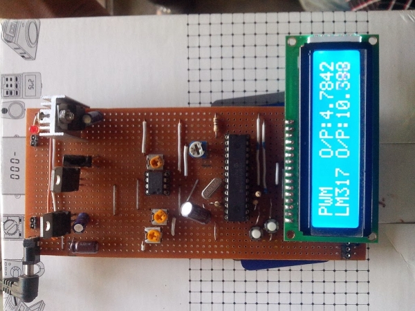
This project builds a small digital DC power supply (5–12V) using a PIC microcontroller to generate PWM, whose filtered and op-amp–amplified DC level drives the LM317 adjust pin. Push buttons change PWM duty to vary output voltage. Components include LCD display, regulators, op-amp, and passive parts; Proteus and MicroC are used for development and PIC programming.
Parts used in the Digital DC Power Supply:
- PIC16F73 microcontroller
- LCD 16x2
- 20 MHz oscillator
- Variable resistors (5k Ω, 1k Ω, 50k Ω)
- 7805 voltage regulator
- 7818 voltage regulator
- LM317T voltage regulator
- LM741 op amp
- Push button switches
- Resistors (1k Ω, 220 Ω)
- Capacitors (47 µF, 10 µF, 1 µF, 0.1 µF)
- Vero board
- Heat sink
In our lab I saw many DC power supply which have a variable knob to regulate the output. I was dreaming to make such a project where I can regulate the voltage using push button.As I am not an industrial level expert so this project is just about a digital DC power supply of small range(5V-12V). You can press push buttons to increase or decrease output voltage.Here we use LM317 to regulate the output voltage. Output voltage is controlled by the PWM output of a pic microcontroller.An OP-AMP is required to amplify the PWM output level. The idea is simple and easy to implement in circuit.
 Necessary Software:
1. Proteus 7.8 Professional
2. MicroC Pro
3. PICKIT 2.61 Boot Loader
Necessary Equipment:
1. PIC 16F73
2. LCD 16×2
3. 20 MHz Oscillator
4. Variable resistor (5k Ώ, 1k Ώ, 50k Ώ)
5. 7805 Voltage Regulator
6. 7818 Voltage Regulator
7. LM317T Voltage Regulator
8. LM741 Op Amp
9. Push Button Switch
10. Resistor (1k Ώ, 220Ώ)
11. Capacitor (47, 10, 1, 0.1 uF)
12. Vero board
13. Heat Sink
 Description:
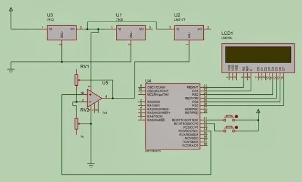
· LM317 can give output of 3-37V . It can change its output voltage according to the adjust pin voltage.
· PWM signal is generated from microcontroller. The signal is applied to RC low pass filter which makes a DC voltage level.
· This voltage is applied to Op Amp to get required gain.
· This amplified voltage is applied to LM317 adjust pin.
· From microcontroller we adjust the width of PWM signal. More width gives higher DC level.
· It also changes the adjust pin voltage which controls the output of LM317.
Source : Digital DC Power supply using PWM with PIC microcontroller
- How is the output voltage varied in this power supply?
The PIC microcontroller varies PWM duty cycle; after RC filtering and op amp amplification the resulting voltage is applied to the LM317 adjust pin to change output voltage. - Can push buttons be used to control the output voltage?
Yes, push buttons are used to increase or decrease the PWM duty cycle from the microcontroller to change output voltage. - What voltage range can LM317 provide in this project?
LM317 can give output from about 3 V to 37 V, though the project targets a 5 V to 12 V range. - Does the PWM output go directly to the LM317 adjust pin?
No, the PWM is first passed through an RC low pass filter to produce a DC level, then amplified by an op amp before applying to the LM317 adjust pin. - What op amp is used to amplify the filtered PWM voltage?
The project uses an LM741 op amp to obtain the required gain. - What software is necessary to develop and simulate this project?
Proteus 7.8 Professional, MicroC Pro, and PICKIT 2.61 Boot Loader are listed as necessary software. - What passive components are required for the circuit?
Resistors (1k Ω, 220 Ω) and capacitors (47 µF, 10 µF, 1 µF, 0.1 µF) are required along with variable resistors. - Is a heat sink required for this power supply?
Yes, a heat sink is listed among the necessary equipment, implying thermal management for regulators like LM317T.