Summary of A RGB LED Matrix Clock
Summary: A PIC32MX250F128B-based wall clock using a 32x32 Adafruit RGB LED matrix was built with IR remote control, serial PC time sync via Python, and an RTCC-driven oscillator. Features include digital and analog displays, stopwatch/alarm groundwork, a modular LED matrix library with graphics/fonts, IR decoding (NEC protocol), and UART communication. Display runs at ~456 Hz using binary code modulation; some RTC oscillator drift and a red-channel upper-half flicker remain to be fixed.
Parts used in the RGB LED Matrix Clock:
- PIC32MX250F128B microcontroller (Microstick II)
- Adafruit 32x32 RGB LED matrix display
- 32.768 kHz external oscillator circuit
- TSOP38238 IR receiver sensor
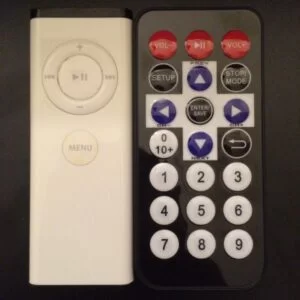
- Adafruit Mini IR Remote (and Apple Slideshow Remote for testing)
- Sparkfun FTDI Basic Breakout (serial to USB adapter)
- Solderboard and supporting passive components (including 330 Ohm resistor)
- Wiring and connectors for matrix interface (data, clock, latch, OE, row select)
- Breadboard/PCB mounting hardware and Microstick II housing
Introduction
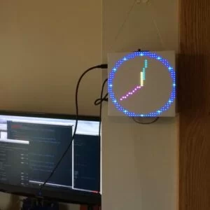
In today’s world of rushed schedules, time is something a ton of people are in constant need of keeping track of. A very good method for keeping track of the time is to have a wall clock. But what if you want a clock that’s different from all the others, or something that will stand out and make your friends say “Hey, that’s pretty awesome!” That’s precisely what we set out to make when we undertook this project. Using the PIC32MX250F128B microcontroller, we built a wall clock that is made from a 32×32 LED Matrix. The clock comes with an IR remote that can control a variety of customization options and smaller features such as a stopwatch and alarm. It also has a serial channel that can connect to a PC to update the time to match your PC internet synced time.
This project was completed over a five-week period for the ECE 4760: Designing with Microcontrollers class under Professor Bruce Land.
High Level Design
Overview
Our project runs off of a PIC32MX250F128B microcontroller, which handles all the controls and processing of data for the 32×32 LED Matrix. An Oscillator crystal handles the realtime-keeping component of the clock, and an IR reciever handles the input from our IR Remote Controller. We also have a serial connection to a PC so we can update the time to match the internet-regulated standards that most PCs sync with on a daily basis. All of these components come together to create the LED Matrix Clock we have designed, and we will go into more detail on these below.
Rationale
The idea for this project arose from the growing popularity of home appliances being both programmable and connected to the internet. As technology continues to evolve and become cheaper, more and more homes and buildings are incorporating these appliances that can be controlled through the internet, such as the Nest home heating unit and the Phillips Hue lighting system. We believe that this LED clock would be a great addition to a home that utilizes internet connected components. The our display could provide a central status hub that reports the status of various other components in the house as well add to a modern technological atmosphere.
While we did not accomplish the ambitious goal of creating an internet connected centralized display this semester, we did build a self contained and novel device that works as functional clock. This is the first step in creating a more useful display and as will be discussed later on, hopefully the start of an on going project to add upon this clock that will make it go above and beyond the exciting wall clock.
Standards
Our project does not (as of this time) utilize RF communications or other regulated technologies, and therefore we could not find any pertinent standards to reference. We had anticipated finding standards for infrared remote technology but again, while we did find some standards used by various companies, we did not find any widely adopted standards that would be relevant to include with our project.
Relation to Existing Works
This project can and should be seen as very similar to the many LED Matrix displays. There are tons of creative LED Matrix projects of every kind, however, they are almost all done by hobbyists who either do not actively share any code or are completely opensource. Additionally, the vast majority of these hobbyist projects are done using the Arduino or more powerful systems such as a Raspberry Pi or FPGA, the former being very easy to work with and the later being highly performant for larger displays. At the onset of this project we were unable to find any documented projects using both the PIC32 architecture and a 32×32 RGB LED matrix. Everything we have done, excluding the resources referred to below, has been our own invention, inspired by our own interests and our peers’ ideas.
Hardware and Software Trade-offs
Our project relies heavily on software. One major trade-off we had to decided between hardware and software was for the time keeping. We ran into an issue with the Pic32 RTCC module running too fast. It ended up being an issue of capacitance affecting the crystal (an affect of working on a breadboard we suspect). However, at that time we decided to try and use the UART serial interface to power all time keeping ability. In other words, a computer with a serial connection would send time updates over UART every second (or faster) in order for our system to update the display. We discovered that this is possible (we managed to get very good accuracy using this method). In the end though, once we fix the oscillator issue, we decided to use the pic32’s RTCC unit instead. The benefits of this being that the system is now less coupled to a serial tether to a computer. Relying on software on the computer to send the time updates meant that if you turned off your computer, software on either the computer or the microcontroller failed, or a serial device lost connection the clock would stop telling time. Meanwhile, the computer clock is typically internet synced and always accurate but the major reliability issues spurred us to pick the best of both worlds where the RTCC is used to keep time but it confirms the time with the computer periodically if a serial connection is present.
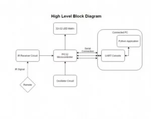
High Level Block Diagram
The block diagram below shows how the various components of our project interact with each other on the highest level. The Python Application handles the syncronization of time with the PC’s system time, but all data from the PC is eventually fed back to the PIC32 to be processed.
User Interface
The user interface for our project consisted of an Adafruit Mini IR Remote, which would control the clock’s various functions based upon which button was pressed. Additionally, the serial interface would allow for the time to be manually set via a UART console. As the project stands now, the IR remote controls the toggling between the Digital and Analog views of the clock as well as between each of the various test images seen in the Results section below. Simply press the Left and Right arrow keys to change between the different views.
Ideally, we would have used the IR Remote to control a menu interface that would come up on the LED Matrix, but due to time constraints, this feature was not implemented. However, it would be very simple to add on to the current control system just by adding in additional command handlers for the various buttons on the remote.
Hardware
Hardware Overview
The hardware for this project included several components. The most notable component is the Adafruit 32×32 RGB LED matrix display. The construction of our final product revolved around getting all the hardware bundled together on the back of the matrix so that it could be hung on a wall or stood up on a surface. In addition to the matrix and its control components (displayed in the image below) we also used two IR remote units for remote control.
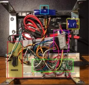
Back side of the matrix clock showing the various highlighted hardware components. Green The Microstick II housing the PIC32 microprocessor. Red The solderboard circuit for the realtime clock oscillator. Magenta The connection for the RGB LED matrix display. Yellow The serial to usb adaptor. Cyan The IR receiver mounted to be visible from the front of the matrix.
The circuitry can be broken down into each component used below. The schematics for the circuits can be found in the Schematics Appendex section. All Pin connections to the MCU are specified here in the table below.
| Device | Pin(s) | MCU Pin(s) | Function |
|---|---|---|---|
| IR Reciever | SIGNAL OUT | 13 | Input Capture 1 |
| 32.768 kHz Oscillator | SIGNAL OUT | 11 | SOSCI |
| LED Matrix | R1, G1, B1 (color data) | 4-6 | IO |
| LED Matrix | R2, G2, B2 (color data) | 16-18 | IO |
| LED Matrix | CLK (data clock) | 2 | IO |
| LED Matrix | LAT (data latch) | 3 | IO |
| LED Matrix | OE (output enable) | 3 | IO |
| LED Matrix | A, B, C, D (row select) | 7, 14, 25, 26 | IO |
| UART | TX | 22 | UART 2 Recieve |
| UART | RX | 21 | UART 2 Transmit |
RGB Matrix
The RGB LED Matrix has a five part wire interface:
- 6 wire channel for writing two RGB LED values at a time – you can only write on or off for each of the red, green, blue values at each pixel
- 4 wire row selection – only two rows are on at a time these bits select which rows, the binary value 0 would turn on 0 and 16, 1 would be 1 and 17, etc.
- A clock signal – indicates that the color values should be latched for the next pixel
- A latch signal – indicates that we are done writing the selected row and the values should be latched and displayed
- A output enable signal – indicates that the currently selected row should be on
The pins these connect to on the PIC32 are listed in the table above.
IR Sensor
The IR circuit was relatively simple, requiring only the TSOP38238 IR Receiver Sensor and a 330 Ohm resistor to protect the PIC32 in case of a surge. The IR reciever simply outputs pulse signals on Pin 13, that we pick up in software as described in the Software section below. Additionally, we made it compatable with the Adafruit Mini IR Remote as well as a standard Apple Slideshow Remote.
Having two remotes available to us allowed for some interesting ideas for some two-player games to be made, but we didn’t have enough time nor resources to implement this. However, it was great for debugging purposes to have one for each group member!
Serial Connection
The serial to usb connector we used was the Sparkfun FTDI Basic Breakout. We use this chip due to its compact size and separation from a USB cable so that we can use the clock without a serial tether and not have to manage the cable. The TX/RX is connected to the PIC32 microcontroller on pins 22 and 21, respectively with the appropriate PPS configuration selected on the microcontroller.
External Oscillator
The circuit for the External Oscillator manages the Real-Time clock for timekeeping whenever a connection to the PC is not present. This circuit was graciously donated to us by our classmate Udit Gupta. In short, it creates a 1 second pulse signal, which we use as a clock to handle our second-counting via the input on Pin 11.
Software
Overview
The software is the largest part of our project and is almost more of a deliverable than the device itself. We spent a large amount of time creating a standalone library for the LED Matrix display as well as making the project as well broken into logical components as possible. The idea is that anyone can fork our GitHub Repository and easily start customizing the system as they see fit. Towards that goal it was heavy priority to make the project as clean as possible and modular so that in order to changing the use of any component (display being drawn, serial use, rtcc use, IR input, or other) is very simple.
The software breaks up into the following components: LED Matrix Control Library, IR Signal Decoding/Handling, Realtime Clock and Calendar, Serial Interface with PC, and the Python Time-Sync Application. Each part of the software works in unision with each other in an effiecent manner.
Controlling the Matrix
The most challenging part of this project was developing the control library for the Adafruit 32×32 RGB LED matrix. The matrix itself does not come with any datasheets or product guides indicating how to control it. Fortunately, there are several helpful guides for how to use this matrix with the Arduino from Sparkfun and Adafruit as well as a description of the findings of what was found when the hardware was reverse engineered on this page. Additionally, there is an Arduino library written for this matrix. Even with all of these resources it was a challenge to get the display working well.
Matrix Display Library
The first step in porting the Adafruit Arduino library for the PIC32 was figuring out exactly what the library does to drive the display. We did this by hooking up and Arduino an playing with the scope to see what the Arduino was outputting to the matrix. Thankfully the library also includes helpful comments to aid in understanding the reasoning behind much of the code. This is vitally necessary since much of the code is highly optimized in order for the many matrix control wires to be output at a fast enough rate to achieve acceptable visual quality and reduced CPU usage. In the code base this is all part of rgb_matrix.c/h.
Here I will give a brief overview of the LED Matrix control interface and the control library. Better documentation can likely be found at the resources above focused on this topic. Using the wires specified in the hardware section if you wanted to write data to display colors on only two rows of leds (0 and 16) here would be steps:
- Set the color channels for the colors you want for the first pixel (column) 0 (so channel one would be the pixel (0,0) and channel two would set pixel (0,16).
- Set the clock signal momentarily then clear, latching that color values.
- Repeat 1 & 2 for each column from 0 to 31.
- Set the latch signal and the output enable high. This will latch the new RGB values to the led controllers and disable the output.
- Clear the latch and the output. This will re-enable the output with the new color values displayed.
In order to get a wider color range (12 bit in this case) and display flicker free frames, the process of writing values to the matrix must be done on an accurate schedule as fast as possible. This means interrupts and a timer must be used to drive the display. In order to get 12-bit color from just setting LEDs on or off we use Binary Code Modulation. So since we are doing the entire matrix update in an interrupt to achieve precise timing for binary coded modulation this means we have to be as quick as possible so that the CPU is not always updating the matrix and has time for other tasks such as actually drawing what to display. So to accomplish a very fast ISR there are some tricks that are used. The first is arranging the matrix buffer so that we can read a memory value and immediately write it to an output port without having to manipulate bits first. The second is to make use of the SET/CLEAR/TOGGLE registers for all of the PIC32 control registers which allow us to modify bits in ports without first reading them to maintain the other bit values. Unfortunately, this means there is some inflexibility in the control library such the control pins are mapped to indices in the matrix buffer and with the current scheme you can only use the pins that are setup for it. In further iterations, macros might be used in order to allow some flexibility in the pins chosen for the matrix color control Finally, we ensure that loop unrolling and optimizations are on so that the loops to write to the array are as efficient as possible and this was verified in disassembly. More about the actual timing considerations is discussed in the results section.
With an ISR to write the values stored in a matrix buffer, we can now write values to this buffer and the matrix will display those values stored in the buffer. But since this buffer is being read very fast by the ISR and might not be updated quickly by the main program, you will actually see individual pixels change on the display as they are written by software. This affect is undesirable and to remedy it we use two display buffers. One called the back buffer and one called the forward buffer. We always write to the back buffer and read the current pixels to display from the forward buffer. When we want to update the image, we set a flag that is read by the ISR after finishing drawing the full matrix. The ISR swaps the buffers by simply swapping the pointers to them so it now begins drawing the updated buffer. This means that animations can be very smooth.
Matrix Graphics Library
The matrix display library only gives a few functions to write to the matrix, drawPixel and fillScreen. While powerful there is many things that we want to be standard and not have to think about as a programmer using the LED matrix display. Thankfully, there was also a library providing this for the Arduino and since these functions are more high level they were much easier to port over. Additionally, the ECE4760 TFT display library is actually another port of the Adafruit graphics library to standard C and the PIC32. Therefore after cleaning it up and adding a few additional features we were able to use this library to draw lines, shapes, and text to the display with easy to use functions.
One of our additions to the graphic library was a new font class. We needed a smaller font in order to fit more information on the screen. Therefore, we found an opensource 3×5 font class and added it to the library. This required converting a BDF font file into a C data definition to be used by the microcontroller. To accomplish this we wrote a python script to take in the font definition file, parse it, and write out the hex code values that can be used as a C array definition the bitmap pixels to draw for each character. Additionally, we generalized the printing functionality such that adding new fonts will not be so difficult.
Matrix Library Demos
In addition to creating the drawing libraries, we also ported and added some of the matrix display tests. As mentioned we wanted to have a standalone library. Part of that is having tests to bootstrap any user of the library. The Adafruit tests we ported test shape drawing, color spectrum, and text. We also added some of our own to test rendering images and colorlevels.
Clock Graphics
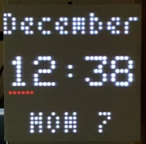
Since we are building a wall clock system, we need to have the clock faces to display. We added a clock graphics library. This is essentially just a collection of functions that were used to create the two clock faces (digital and analog) we have created during this project but we fully intended to make it easy to swap and tune the clock faces to be customizable.
Handling IR Signals
To get the remote control working with our project, the idea was to be able to decode pulses sent from the remote, via an IR Receiver that would translate the signal into a digital signal. This digital signal would then be fed into the Microcontroller and decoded accordingly. Fortunately for us, the TSOP38238 IR Receiver Sensor came with a built-in differential OP-Amp, and so it would output the square pulses for us from the beginning. It was also tuned to 38 KHz, which was what our remote transmitted at.
The Adafruit Mini Remote Control that we used uses the NEC IR encoding type for transferring the data of which button was pressed. The protocol is relatively straightforward and is explained with stellar detail over at this website.
The difficult part for us, was figuring out the optimal way of decoding these incoming pulses on the Microcontroller in a way that wouldn’t interfere with the large CPU demand of the LED Matrix code. Adafruit graciously included an Arduino tutorial on how they decoded their inputs here. However, this tutorial wasn’t A) optimized for our PIC32, and B) ran the entire code within a loop that would interfere with our LED Matrix code.
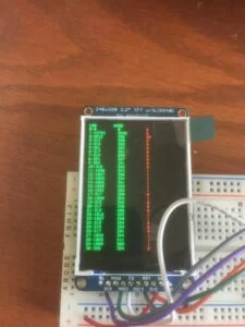
To this end, we decided to utilize the same ideas we used in the Lab 1 Capacitance Meter. We would make an ISR that would trigger pulse captures, and then when we were certain that an entire pulse was captured, we would decode it. To do this, we had to utilize an Input Capture on RB13 of the PIC32. The setup for this was just as it was in Lab 1, except we trigger the timer capture on every single edge (rising and falling), because for the initialization pulse, we need both the high and the low widths. Once I had captured all the pulse times, I would then store them in an array for decoding. The following image is from the beginning stages of my work with this. Basically, the values you see in the column marked “LOW” are the timer counts for when the signal pulse was low, “HIGH” when it was high. I had set the timer with a prescalar of 64 on a 40 MHz clock, so each count corresponds to about 1.6e-6 seconds. This is the raw timer counts data, and after messing around with it for a while, I determined the following threshold values for various pulses:
- Initialization Pulse: HIGH 5550 – 5850 counts followed by LOW 2650 – 2950 counts
- Repeat Pulse: HIGH 5550 – 5850 counts followed by LOW 1250 – 1550 counts
- Logical 0 Pulse: After Initialization Pulse, LOW 200 – 500 counts
- Logical 1 Pulse: After Initialization Pulse, LOW 900 – 1200 counts
These thresholds are much higher than probably what is needed, but it helps to allow for a large variation in the case of signal interference, especially whenever you use the remote from a distance.
The red numbers are the decoded versions of the pulses to the right. The 52 corresponds to the Initialization Pulse. There was an anomaly with our remote in which the logical inverse of our address (0x00) was always (0xFC) instead of (0xFF). We worked around this by just ignoring the logical inverse portions of our signal in the final decoding stage. Once everything was decoded into 1s and 0s, it was easy to then just check that the incoming address was 0x00, and translate the 8-bit opcode to a string.
Realtime Clock and Calendar
The realtime clock and calender was very easy to setup after reading through the PIC32 documentation and examples online. Using the plib.h functions all that needs to be done is call the corresponding RTCCOpen() function and the RTCC should initialize and be ready to provide the time. Now, this is using a very trivial setup, however. A better application would use a drift correction algorithm to calculate the errors of the 32.768KHz oscillator that drives the realtime clock. This will be discussed further in the results section.
In addition to simply enabling and reading the values directly from the RTCC, we added a set of date/time functions in datetime.c to ease using the dates and converting between the Binary Coded Decimal values provided by the hardware RTCC. This also includes helpers to convert to strings to display dates.
Serial Interface
The serial interface we added to communicate with and set the time on the PIC32 is very simple. We use the Cornell Protothreads UART functions to read and write from the UART in a nice threaded protocol. We did find, however, that using the PT library to send serial data was a bit cumbersome and as such added some very convenient wrapper macros to simplify the sending of data using the PT library (these are in the serial extensions file, serial_ext.h). The actual communication interface over serial consists of four messages. The PIC32 will send a “gtd” message (get time date) to the computer when it needs a time update. If the computer is connected and listening, it should respond with a time and then a date message. The time message just consists of the format:
“t <hours>:<minutes>:<seconds>”
This corresponds to the human readable time that the PIC32 should update to. The date is the same idea but the message format is:
“d <month>/<day of month>/<year>-<day of week>”
The last message that can be sent is a “BAD CMD” from the PIC32 to the computer. This indicates that a message was received that did not match either the time or date pattern. Each of these messages must be terminated by a carriage return as a end delimiter. Without a carriage return the PIC32 will read until its buffer is full and then parse the input which will result in an invalid if the max buffer does not match the specified patterns. To parse the patterns a simple sscanf is used with an appropriate format string.
Python Time-Sync Application
In addition to the code on the PIC32, we also had to have an application running on the computer to receive and respond to time/date update requests from the MCU. We wrote a simple application in Python 3.5 using PySerial as the serial communication library. The appication simply waits reading the serial input until it gets a “gtd” message at which point it sends both the time and date. We found that we had to manually add delays to the serial write methods in order to avoid overflowing the PIC32s input buffer. We found that typically unthrottled writes of more than 8 characters resulted in the PIC32 UART receive interface locking up. The ensure that this does not occur under normal operation, we modified the PT UART library to check the UART overrun bit and clear it to restart the UART receiving. We suspect that we were encountering this error more that typically because our large amount of time spent in the matrix display interrupt caused the receive fifo buffer to not get read as often as it would typically.
Matrix Display
The matrix display results were excellent. Due to the PIC32’s faster clock speed (running everything at 40MHz so room to improve further) and memory footprint, we were able to successfully control the matrix at a refresh rate near 450Hz using roughly 30% CPU. This is the CPU time that is required to just update the matrix display, it does not include any time to actually draw anything to be displayed. In order to measure the time in the ISR we added test code to toggle a bit when entering and exiting the ISR then measured the times on an oscilloscope. Since there are four different control flow paths and different spacings of the ISR we measured the ISR for four interrupts and the delay between. The whole period (which corresponds to drawing a single row) takes 137 microseconds and in that time we are in the ISR for 11.6 + 8.8 + 8.0 + 8.0 = 36.4 microseconds. So therefore we are spending 36.4 / 137 = 26.6% of CPU time handling the ISR for the matrix update. Now we have to do one of these updates for each row (16 rows since we write out two rows at a time) so in order draw the entire matrix once it takes 16*137 = 2192 microseconds. This corresponds to a refresh rate of 1/0.002192 = 456Hz. This may seem extremely high since humans it is above the typical frame rate at which humans can notice. However, due to the use of binary coded modulation to get the colors and only two rows of the matrix are lit at a time, this refresh rate is necessary to make the display appear non flickery and as smooth as it is.
The display looks excellent visually for all colors and animations except on scenario. There is some issue with the red color input for the upper half of the matrix. When displaying bright red colors (high amount of red) in the upper half, we end of getting flickering of the red LEDs in the middle of the matrix. Experimenting with swapping ports and with other colors revealed that this is only an issue for the color red and only for the top half of the matrix. We hypothesize that it may be a voltage issue since the matrix is typically uses a logic level of 5V instead of the 3.3V of the PIC32, since we just discoved this issue recently we unfortunately, have not had the opportunity to swap in a logic level converter to see if it makes a difference but that is the next step.
IR Control
The IR Controllers worked fantastically as controls for the Matrix. Although we didn’t get the menu interface in as we intended to, toggling from one view to another was as simple as a single button press.
Using both remotes worked smoothly as expected as well. There were some observed differences between the two remotes that made us consider using one over the other in the future as well. The main observation was that the Adafruit Mini IR Remote was much weaker in its range than the Apple Remote. The Adafruit could only be detected at ranges less than about 5 meters, while the Apple Remote could work at ranges as long as the lab (which is at least 25 meters). However, the Apple Remote encountered some issues with interference with a classmate’s MacBook laptop. Whenever buttons on the Apple Remote were pressed, occassionally PowerPoint would open on their computer. We knew that using the Apple Remote had the potential to interface with Apple computers, but usually a “pairing” in neccessary before the laptop will recognize this. The Adafruit Mini Remote did not have any interference issues with any other devices within the lab. Considering these factors, we decided it might be a better idea to only use the Adafruit Remote in the future, as it’s low power and non-associtivity with existing devices give it lower chance of causing interference with other devices.
The signal interference made an important point when considering which remote to use, which is also why our IR Decoding method always checks the signal address. Both of our remotes used address (0x00). To make sure we didn’t decode other group’s IR signals, we only would accept signals that transmitted with this data address as its target.
Serial Interface
The serial interface works wonderfully with the PIC32 after throttling send rates from the computer and checking the error bits. We now only send a character every 2 milliseconds but we only send 11 characters max with the time and 13 characters for the date. This results in a expected delay of about 22 milliseconds minimum for the time (which is more crucial since we are setting a realtime clock). It then may take additional time for the PT library to wake up the serial thread to actually process the message. We found that adding a second to the time before sending to the PIC32 generally improved the accuracy. We believe that determining the average time for the serial thread to process the message would be desirable but might be overkill since we do not require precise timing.
As an aside, before we got the RTCC on the PIC32 operational, we were able to get the serial interface sending precisely timed updates to the PIC32 to maintain the time very well. This of course has drawbacks of being very coupled to the computer and more failure points but is a good fall back mode.
Realtime Clock and Calender
Our realtime clock and calender unit ended up being less accurate than desired. We did not get a chance to do precise measurements in the lab of the accuracy but we did a extrinsic test of the clock being used for a 48 hour period. For the first, 24 hours the clock started at perfectly in sync with computer time (truth value in this experiment) and was detached from the computer (no serial communication to update). We found that the time was approximately 14 seconds fast after that 24 hour period. This is a huge error of over a minute and half a week and unacceptable for the device we wanted to create. However, the second half the of the test consisted of 24 with the serial tether connected to a PC. For each checkup we made the time was perfectly in sync (as measured by the human eye). So in this case we cannot rely on the real time clock unit for any period of time greater than an hour (half a second loss estimate). We believe this error is caused by issues of packing the oscillator along with the other higher frequency control wires all in the back of the matrix unit, possibly causing interfere and disrupting the timing but without doing the proper testing with a oscilloscope it is hard to determine.
Conclusions
Summary
Our project did a lot of what we set out to do, but didn’t meet 100% of our goals. We intended to have a menu interface that would be controllable via the IR remote that could be used to set Alarms as well. Other than that, though, all of our goals were met with excellent results. An entire control library for the 32×32 LED Matrix was written, including fonts, animations, and shape drawing. The time was kept in an accurate manner, it syncs with a PC’s time, and is displayed in both Analog and Digital fashions. The IR Remote can be used to toggle between various images and the two time displays, with no issues at all. In our opinions, the project met almost everything of what we set out to do, with the groundwork set for much expansion in the future. We are very satisfied with the results, and hope to continue working on this project into the future.
Applicable Standards
Our project did not have any standards that applied to it. We personally did not want our IR devices to interfere with others, and so we decided to use the Adafruit Remote over the Apple Remote to nullify this issue.
Intellectual Property Considerations
We do utilize three libraries in our codebase which were written by others. The first is the Cornell protothreading library. Written by Bruce Land, this library contributes by adding a UART interface and threading system (adapted from the protothreads library written by Adam Dunkels). We have also made modifications to this library to suit our appilication. The second library we used is the Adafruit RGB Matrix Panel Library for Arduino. We used this library as a means of testing and reverse engineering the interface for controlling the RGB matrix. Our our control library for the RGB matrix is heavily based on the concepts from the Adafruit library but re-written for the PIC32 architecture. Finally, we also adapted and added to the Adafruit GFX Library for Arduino. We used an already adapted version of this library (adapted by Syed Tahmid Mahbub and can found at his blog). We adapted it further for the matrix as well as adding additional functions as necessary. All of these libraries are open source and have no restrictions on use provided proper referencing.
We also use a bitmap font definition that is available for opensource use under the MIT license which we have included with our project as required.
Ethical Considerations
Throughout the entire period in which our project was performed, future and prior, all members of our team strictly followed the IEEE Code of Ethics. All decisions within the group were made with the safety of all members and welfare of the public put firstmost. No conflicts of interest were encounted during our project. All data and measurements stated on this page are truthful to the best of our knowledge. Even though no bribes presented themselves, no bribes were accepted, nor would they would have they been. All efforts in this project were intended to improve our group’s understanding of technology, its appropriate application, and potential consequences. Before any movements were taken on the part of the group, thorough research and comprehension was performed to ensure that the project stood within any pertinent limitations. Technical critisim was welcomed and sought by all members in an effort to acknowledge, learn from, and correct errors. Addtionally, all members openly gave technical critism to those who sought it. All outside contributions to this project were properly accredited in the appropriate manner. No person was ever discriminated against for any reason based upon race, religion, gender, disability, age, national origin, sexual orientation, gender identity, or gender expression. No action from any of our members injured anyone, their property, reputation, or employment by false or malicoious action. Lastly, all members assisted colleagues and co-workers in a professional manner to provide helpful development and to support them in following the aforementioned IEEE Code of Ethics. Every possible action was taken to make this project safe, enjoyable, and rewarding for every entitiy involved.
Legal Considerations
To our knowledge, our device does not violate any legal regulations. Pulse transmissions from our two Remotes are from commercially avaiable devices, and are within the 38kHz range common with most commerical IR devices. Use of lab equipment was authorized with prior permission from the lab staff.
Source: A RGB LED Matrix Clock
- What microcontroller is used in the project?
The project uses a PIC32MX250F128B microcontroller housed on a Microstick II. - How is time synchronized with a PC?
A Python 3.5 PySerial application responds to gtd requests from the PIC32 and sends time and date messages over UART to sync the clock. - Can the clock be controlled remotely?
Yes, an Adafruit Mini IR Remote (and optionally an Apple Remote) controls toggling between digital and analog views and other displays via an IR receiver. - How is the 32x32 matrix driven for flicker-free color?
The matrix uses an ISR-driven update with Binary Code Modulation and double buffering to achieve ~456 Hz refresh and 12-bit color appearance. - Does the project include a realtime clock hardware source?
Yes, a 32.768 kHz external oscillator feeds the PIC32 RTCC for standalone timekeeping. - What IR protocol is decoded by the system?
The Adafruit Mini Remote uses the NEC IR encoding type which the system decodes using input capture interrupts. - How does the serial protocol format time and date messages?
The PIC32 expects time as t <hours>:<minutes>:<seconds> and date as d <month>/<day>/<year>-<day of week>, each terminated by a carriage return. - Is there any known display or RTC issue?
Yes, the upper half red channel flickers under bright red and the RTCC showed drift (~14 seconds fast over 24 hours) in testing. - Can the IR remote be expanded for menu control?
Yes, the report states adding command handlers for more remote buttons would allow a menu interface on the matrix, but it was not implemented due to time constraints.