


Summary of DEVELOPMENT BOARD PIC18F2550 PIC18F4550
Summary: This article describes a PIC18F2550 and PIC18F4550 experimental development board. The PCB layouts include selectable power sources, LEDs, buttons, LM35 op amp temperature sensor, EEPROM, relay, L293 motor driver, potentiometer connections, DS1807 clock, header sockets for microcontroller ports, and Proteus ARES and LytA source files for building and testing the board.Parts used in the PIC18F2550 PIC18F4550 Development Board:
- PIC18F2550 microcontroller
- PIC18F4550 microcontroller
- PCB printed circuit board (development board)
- Power source selection components
- LEDs
- Push buttons
- LM35 temperature sensor (op amp referenced)
- EEPROM
- Relay
- L293 motor driver
- Potentiometer connections
- DS1807 real-time clock
- Header sockets for microcontroller port connections
- Proteus ARES project files
- LytA files
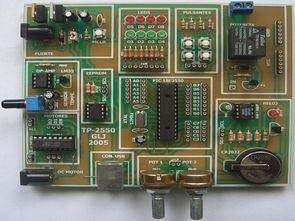
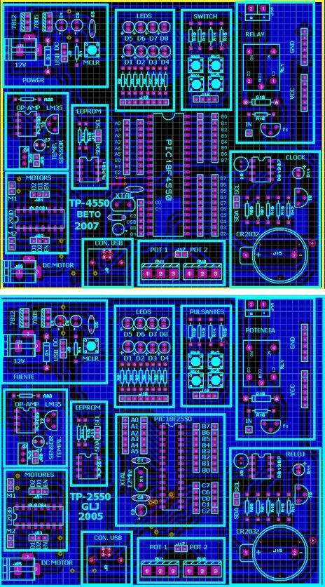
PIC18F4550 and PIC18F2550 prepared for the experiment set of circuit than the regular seems simple, each chapter PCBs indicated on the layout also pretty good easily can be selected power source, LEDs, buttons, op amp LM35, EEPROM, relay, L293 motor drive, potency connections, ds1807 clock in addition there are sections in the header socket connections of the microcontroller’s port. pcb printed circuit drawing of the experimental set PIC18F2550 PIC18F4550 proteus ares prepared by the source. LytA files there.
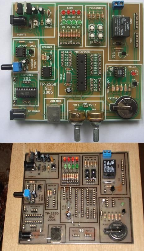
Source: micros.mforos.com/1149907/6089366-construyendo-y-probando-la-tp-2550-placa-de-pruebas-para-usb/ alternative link: development-board-pic18f2550-pic18f4550.rar
- What microcontrollers does the development board support?
The board is prepared for PIC18F2550 and PIC18F4550 microcontrollers. - Can I select different power sources on the board?
Yes, the PCB layout allows selectable power source options. - Does the board include indicators and input switches?
Yes, the board includes LEDs and push buttons. - Is there a temperature sensor on the board?
Yes, the LM35 temperature sensor is included. - Does the board provide EEPROM and clock support?
Yes, it includes EEPROM and a DS1807 clock section. - Can I drive motors with this board?
Yes, the L293 motor driver is provided for motor drive connections. - Are there connections for potentiometers?
Yes, there are potentiometer connection points. - Does the project include PCB and simulation files?
Yes, PCB drawings and Proteus ARES and LytA source files are provided.
Related projects
PICDEM FS USB CDC Evaluation Board using PIC18F4550 with Proteus Simulation
Introduction The PICDEM FS USB CDC Evaluation Board is a practical microcontroller project built around the PIC18F4550, designed to demonstrate USB communication...
Peripheral Tutorials · PIC18F4550PICDEM FS USB Mass Storage Device using PIC18F4550 with Proteus Simulation
Introduction This microcontroller project demonstrates how to simulate a USB Mass Storage Device (MSD) using the PIC18F4550 in a Proteus simulation environment....
Development Boards & Kits · PIC18F2550Pinguino Project: A PIC Microcontroller Based Arduino
This is a complete tutorial to make a PIC Microcontroller based Arduino. This is a complete tutorial to make PIC microcontroller based...
Development Boards & Kits · PIC18F4520Voltage Measurement with A PIC Microcontroller
Voltage Measurement with PIC Microcontroller articulates a methodical framework for facilitating analog voltage measurement using the PIC18F4520, an advanced member of Microchip’s...
Development Boards & KitsUltra-Low Power: Microcontroller Standby Current to 130uA with OPEnS Power Control Board
At the OPEnS Lab, a key focus for our projects is achieving exceptionally long battery life. This was particularly true for the...
Development Boards & KitsAn Integrated Approach to Developing Applications with Microchip PIC Microcontrollers
1. Introduction In our daily lives, a variety of devices such as telephones, household appliances, and cars incorporate "smart" electronics, typically manifested...

Ibrar Ayyub
I am an experienced technical writer holding a Master's degree in computer science from BZU Multan, Pakistan University. With a background spanning various industries, particularly in home automation and engineering, I have honed my skills in crafting clear and concise content. Proficient in leveraging infographics and diagrams, I strive to simplify complex concepts for readers. My strength lies in thorough...