Summary of DC motor control with Joystick and PIC16F877A
This project demonstrates controlling a DC motor using a PIC16F877A microcontroller, a joystick for analog input, and a 74LS138 DEMUX to manage an H-Bridge. The system reads joystick voltage to calculate PWM duty cycles and direction, enabling forward or backward rotation. While initially configured for one motor, the design supports expansion to four motors via the DEMUX.
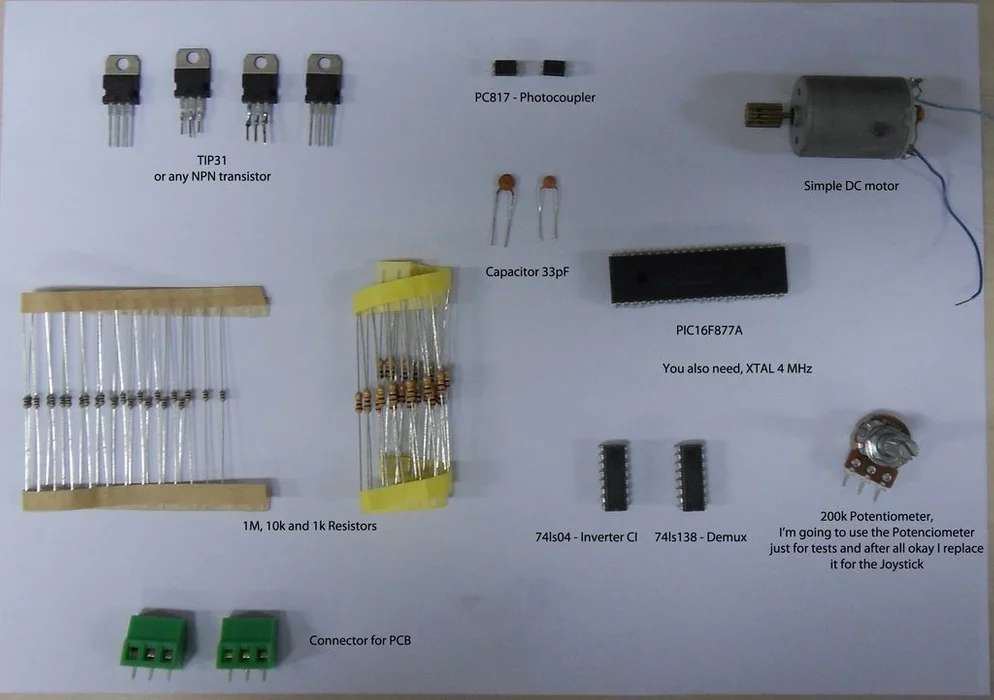
Parts used in the DC Motor Control Project:
- PIC16F877A Microcontroller
- Joystick (used as potentiometer)
- H-Bridge circuit
- 74LS138 DEMUX
- TIP31 Transistor
- Inverters
- Power Supply (5V for PIC, 15V for H-Bridge)
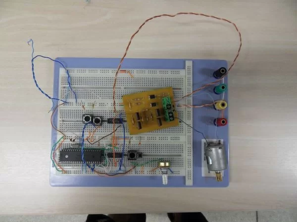
This is one project that i’m doing, now I’m going to show how to do it only for one motor, but i’m using and DEMUX to in the future use 4 motor.
The project is simple, it uses the pic to control the DEMUX and the DEMUX control the H-BRIDGE that control the motor forward or backward.
Step 1: Part List
The itens that you will need is in the picture below.
Board not in picture, but you will need right?
Step 2: Schematic
The H-Bridge schematic, sorry about the mess.
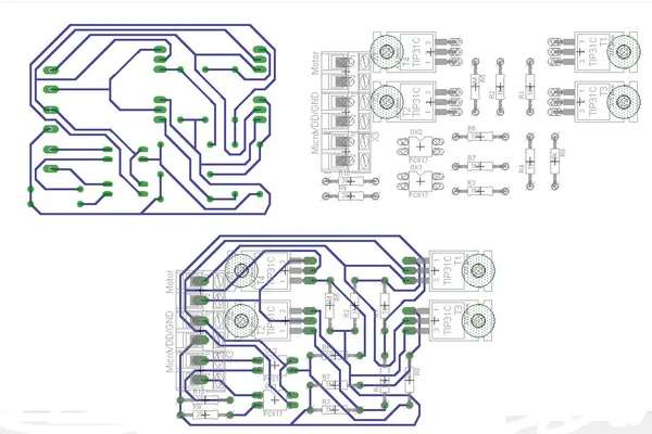
The print version is in PDF file
My motor works with 15V, but with the TIP31 I can put much more than that.
Step 3: Schematic
This is the schematic for the connections with the PIC16F877A.
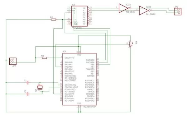
The JP1 is VCC and GND, the JP2 is where you connect the motor, inverter is necessary for this, because the DEMUX work in logical level low, but if you have one thats work in high you can remove inverters ports.
The Pot is the ANALOG input, where I will connect my Joystick.
The PWM is the port RC2/CCP1 and goes to DEMUX.
The DEMUX is very simple, look in the link below for the datasheet.
http://www.datasheetcatalog.com/datasheets_pdf/7/4/L/S/74LS138.shtml
Step 4: The Code
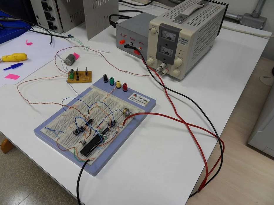
After everything is connected, make sure the supply for PIC is 5V, for my case, supply for the H-Bridge is 15V and the ground of both must have the same GND.
Now my code is very simple. It recive the Voltage from the Joystick that works igual a potentiometer, and calculate PWM duty and the direction of the rotation of the motor.
Donwload the PDF or the TXT file.
Step 5: Conclusion
This is the video demostrantion of the project working, its hard to see but belive me, if every thing is correct the motor will rotate to both directions.
http://www.youtube.com/watch?v=GIPJ-SR7aXI
Source: DC motor control with Joystick and PIC16F877A
- How does the system determine motor direction?
The code calculates the direction of rotation based on the voltage received from the joystick. - Can this project control more than one motor?
Yes, the author uses a DEMUX to allow for future use of up to four motors. - What is the function of the inverters in the schematic?
Inverters are necessary because the DEMUX works at a logical level low, though they can be removed if using a high-level working DEMUX. - What voltage is required for the H-Bridge supply?
The H-Bridge requires a 15V supply, while the TIP31 transistor can handle even higher voltages. - Which port connects to the DEMUX for PWM signals?
The PWM signal connects to port RC2/CCP1. - What must be done regarding ground connections?
The ground of the PIC supply and the ground of the H-Bridge must share the same GND. - Where is the analog input connected?
The Potentiometer or Joystick connects to the ANALOG input labeled JP1. - Does the motor rotate in both directions?
Yes, if everything is correct, the video demonstration shows the motor rotating in both directions.