A Word Clock
**************************************************************************
Major updates – A much better enclosure for this clock has been designed, and a better controller using an AtMega controller now exists. check out
http://www.instructables.com/id/The-Wordclock-Grew-Up/
**************************************************************************
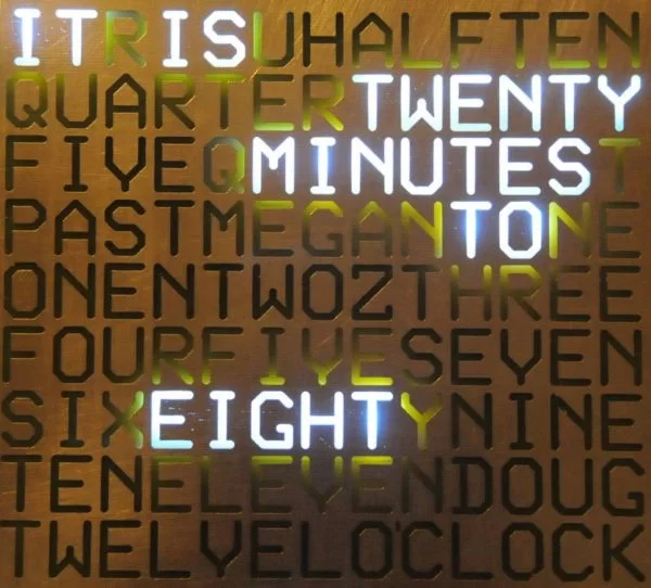
This is a project to tell the time using words.
I saw a cool clock on the Make Blog the other day (http://blog.makezine.com/archive/2009/09/qlocktwo_clock_tells_time_with_word.html), and thought ‘Hey – I can make one of those’, so here it is!
There are two new photos of a completed clock kit, mounted in an enclosure, and hanging in my dining room. The clock module in the center is 150mm x 150mm, and the enclosure surround is 300mm x 300m craftwood, painted with automotive paint. I think that it looks really great!
I am now able to sell all sorts of components, ranging from complete clocks, through to kits, through to individual modules and components. Please visit my web site www.dougswordclock.com for further information.
If you want an arduino version of this project, then have a look here: http://www.instructables.com/id/The-Word-Clock-Arduino-version/ |
This version uses a PIC microcontroller.
I am in Australia, where the mains frequency is 50 Hz (50 cycles per second). This clock uses mains to ensure that it stays accurate. I have realised that people in other countries (USA) may want to construct the clock, so I have modified the firmware to cater for 60Hz countries. Just download either the 50hz, or 60hz firmware depending on where you live.
Another update – I have modified the clock to allow Minute LEDs to be used around the edge – Have a look at the last step of this instructable for details.
Construct the Hardware
First, you will have to dowlload the PCB files – they are attached.
I printed the PCBs out using my laser printer, and photocopied the layouts onto PressnPeel Blue film. You can use any PCB manufacturing process you like.
Having etched, and drilled the boards, populate them as shown in the two photos.
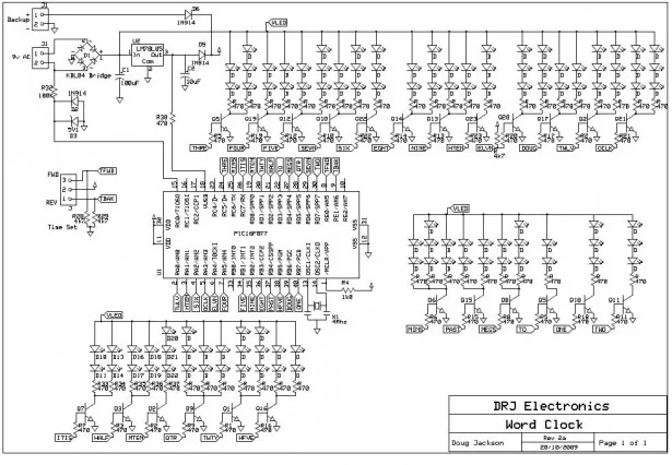
I have attached the schematic diagram, and the PCB layout.
Both boards are connected together using jumper wires along the edge.
DO I *REALLY* USE 360R AND 36R RESISTORS?
As an update, I have been using Blue Flat Top LEDs, with a forward voltage drop of about 3.3v @ 20mA. The supply that I was using was about 10.5VDC. With the original design, with 2 LEDs, the voltage drop across the LEDs was 6.6v, meaning that 3.9v was being dropped across the resistor (11-6.6). With a 360R resistor, this limited the current to 10.8mA, and with 3 LEDs, the voltage drop across the LEDs was 9.9v, meaning that 0.6v was being dropped across the resistor (11-6.6). With a 36R resistor, this limited the current to 16mA.
What I have subsequently discovered is that with supply voltages of 12V, the current through the leds ends up being way too high (15 & 58mA), which is a problem.
In my most recent versions, I have setled on 680R for the 2 Leds and 270R for the 3 Leds, providing 7.9 and 7.8 mA respectively. Much lower current, and still ample illumination.
Make the Stencil
Just etch the board using the same method you used for the controller and display PCB, and lacquer it to protect the front of the display.
In order to reduce light breakthrough to adjacent words, I used 30mm baffels made from spare PCB stock. These were held in place using hot melt glue.

Step 3: Program the Micro
Just use whatever PIC programmer you use.
The Hex file is attached! Remember to use either the 50Hz or the 60Hz firmware depending on your region.
I have also added support to keep the clock running on battery backup when power is lost.
[Update] – I have updated the 50Hz and 60Hz firmware files – there was a simple coding error that affected the accuracy of the clock.
 wordclock-C-60Hz.hex11 KB
 wordclock-C-50Hz.hex11 KB

