Summary of Crafting a Microcontroller Circuit: From Design to Programming
Summary: The article describes designing, fabricating, and programming a microcontroller board using Eagle, machining and assembling the PCB, and programming an ATTiny via WinAVR/avrdude and FabISP/FTDI tools. It outlines making power regulation, ADC channels, Vout pins, and ICSP/servo connectors, and details workflows for blinking LEDs, button input, serial printing, and servo control using C and Assembly. The author recommends tutorials, Sparkfun libraries, stepwise learning, and starting from known-working code to reduce frustration.
Parts used in the Crafting a Microcontroller Circuit: From Design to Programming:
- PCB board designed in Eagle
- Power regulation components (voltage regulator and passive parts)
- Four ADC channel connectors
- +/− Vout pin bank
- ICSP connector
- Two servo output connectors
- ATTiny microcontroller (hello.ftdi.44 board)
- FabISP programmer (USBtiny)
- FTDI cable (for power and serial)
- 9VDC power source
- Multimeter (for verification)
- Sparkfun Eagle library components (recommended)
Official Assignment Description
For this week’s project, the task was to create a board, which was relatively straightforward once I got the hang of EAGLE’s idiosyncrasies. Afterward, the challenge was to instruct the board to perform a specific task, a process that proved to be quite frustrating. Given my prior experience with Arduino programming, I opted to concentrate on gaining familiarity with a range of programming languages and approaches. My aim was to establish a foundation for making informed decisions about hardware, software, and IDE selection in future projects.
Design, Fabrication, and Programming
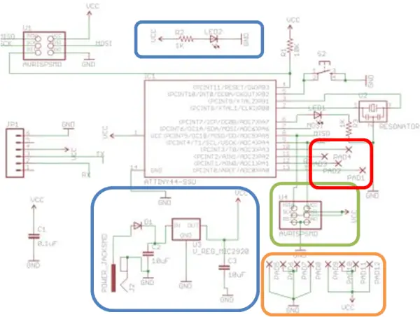
Create the circuit design using Eagle software. Learning and using Eagle was relatively straightforward, but there are some idiosyncrasies within the program. Firstly, ensure that you adjust the grid to the finest setting to facilitate precise wire placement. Secondly, verify that the components you intend to use are available in the Fab class inventory, even though you might not find the exact parts in the Fab Eagle library (typically, standard-sized components are 1206). I highly recommend using the Sparkfun Eagle library, which offers clear documentation for various components. In my design, I included a power regulation circuit (inspired by similar boards), indicated in blue, established more accessible connections for four ADC channels (shown in red), integrated a bank of +/-Vout pins (highlighted in orange), and added an ICSP connector for two servo outputs (depicted in green). For additional assistance, you can refer to this helpful Eagle tutorial: http://www.sparkfun.com/tutorials/109
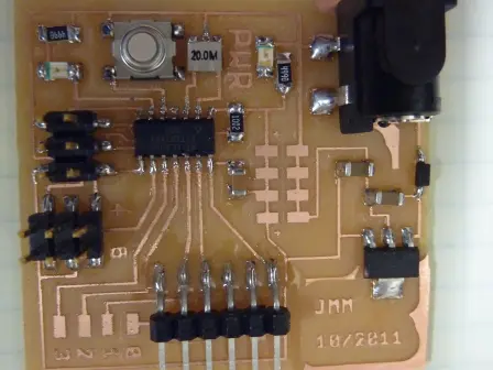
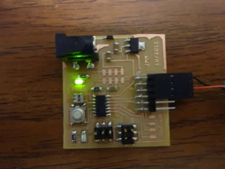
Machine the circuit board and assemble its components. Verify the connections using a multimeter and assess the power circuit using a 9VDC power source.
Step 3: Now, it’s time to delve into programming, which might be the most challenging part of the process. Not because it’s inherently difficult, but because there are numerous ways to approach it, and countless potential pitfalls. In my experience, I discovered that two tutorials were particularly useful:
1. “Understanding AVR”
2. “Beginning Embedded Electronics 2-4”
Here’s the basic sequence I followed to achieve the LED blinking on my project:
1. Employ WinAVR and Programmers Notepad to create a sample file named “test.c.”
2. Utilize a Makefile to generate the “test.hex” file.
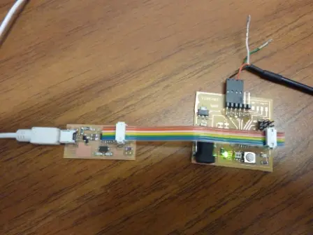
3. Connect the FabISP board to my computer’s USB port and ensure that the appropriate driver is installed. It should be recognized as “USBtiny.”
4. Connect my “hello.ftdi.44” board to the FabISP board using the IDC ISP cable, ensuring proper orientation. Since we desoldered one of the jumpers on the FabISP board, I had to supply external power to the board via the FTDI cable.
5. To upload the “test.hex” file to my “hello.ftdi.44” board, I executed the following command in the command prompt: “avrdude -p t44 -c USBtiny -U flash:w:test.hex” (Alternatively, you can perform this step by selecting “Tools->Program” in Programmers Notepad).
Step 4: Experiment with the program using Assembly language. You can find valuable resources for learning on this website, along with a helpful document containing illustrative examples.
Explore the “AVRAssembler1.asm” file.
Step 5: Attempt a different program, this time returning to the ‘C’ programming language. The objective is to illuminate the LED upon pressing the button.
Explore the “button.c” file.
Step 6: Proceed with a program aimed at establishing one-way Serial Communication between your project and your computer via the FTDI cable. In my case, using Windows 7, I had to install Tera Term on my computer to facilitate this.
Program File: “printing.c”
Step 7: Now, venture into crafting a program that can control two servos and provide status updates for debugging purposes.
Program File: “servo.c”
Useful Insights and Advice
This week can be particularly challenging if you have limited experience with microcontroller programming. I’d recommend focusing initially on mastering the process required to program your ATTiny. Then, take a step-by-step approach when crafting your own programs, rather than attempting to tackle everything all at once.
One of the most frustrating aspects of microcontroller programming is the abundance of methods to achieve the same goal, but only a few of them are forgiving of errors. It can be perplexing because different individuals on the internet advocate distinct approaches, making problem-solving a challenging endeavor. If you prioritize results over an in-depth understanding of programming, it’s advisable to commence with a known-working program (possibly from someone else) and build upon it. While starting from scratch is a valuable skill, it may introduce substantial frustration into your week.
Working with C and Assembler for basic operations like pin manipulation is relatively straightforward. However, it becomes notably more challenging when handling more complex operations, especially those involving memory. After this week, I’ll be transitioning to Arduino, unless memory constraints impose limitations. Thank you for your guidance!
Source: Crafting a Microcontroller Circuit: From Design to Programming
- How do I create the circuit design for this project?
Use Eagle software, set the grid to the finest setting, verify component availability in the Fab inventory, and consider using the Sparkfun Eagle library. - How should I verify the assembled board?
Machine and assemble the PCB, then verify connections with a multimeter and test the power circuit using a 9VDC power source. - How do I compile and upload a test program to the ATTiny?
Create test.c with WinAVR and Programmers Notepad, use a Makefile to make test.hex, then upload with avrdude -p t44 -c USBtiny -U flash:w:test.hex or Tools->Program in Programmers Notepad. - Can I use the FabISP to program the hello.ftdi.44 board?
Yes; connect FabISP to USB, ensure the USBtiny driver is installed, connect hello.ftdi.44 to FabISP via IDC ISP cable with correct orientation, and supply external power if required. - What resources helped with understanding AVR programming?
The author found the tutorials Understanding AVR and Beginning Embedded Electronics 2-4 particularly useful. - How can I get serial communication between the board and my computer?
Create a program like printing.c and use the FTDI cable; on Windows 7 the author installed Tera Term to receive serial output. - How do I implement LED blinking and button input?
Start with a simple test.c for LED blinking, then use button.c to light the LED when the button is pressed. - Is it recommended to start from scratch when programming?
The article recommends starting from a known-working program to reduce frustration, then iterating toward your own code. - What languages did the author use to program the ATTiny?
The author used C with WinAVR and also experimented with Assembly language examples like AVRAssembler1.asm. - How can I control servos and get debugging info?
Use a program such as servo.c to control two servos and provide status updates for debugging.