Summary of contruction of personal Radar System using PIC MIcrocontroller PIC18f452
This article details a hobbyist Personal Radar System utilizing the PIC18F452 microcontroller. The system employs an IR range sensor to detect proximity within specific distances (ranging from 4cm to 5.5m) and displays results on an LED array. The microcontroller processes sensor data to operate the radar functionality, which is designed for close-proximity detection at a 90-degree angle.
Parts used in the Personal Radar System:
- LM7805 5v Voltage Regulator
- PIC 18F452 Microcontroller
- GP2D120 IR Sensor
- 4 or 8 MHz Oscillator
- SPST Switch
- 1µF Capacitor
- 30 pin SIPs
- 5x 74LS373 Latches
- Prototype Board
- Solder
- 36x LEDs
- Wire 30 AWG
- Wirewrap Tool
- Soldering Iron
Personal Radar System using PIC MIcrocontroller PIC18f452 is a microcontroller hobby project. The circuit diagram of radar is attached here below seemed a little bit simple schematic but you need careful reading of PIC18f452 radar circuit to avoid any damage. The project of personal Radar System using PIC MIcrocontroller PIC18f452 uses three main devices to create the personal radar system which are listed as below: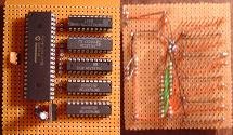
1. The IR Range sensor gives output,
2. The pic microcontroller PIC18f452 processes the necessary instruction to carry out the operation smoothly.
3. The displays the output on the led array. This is the output of the radar system.
Functionality of IR Radar SYSTEM :-
The main function of the project is to create and have a simple functionality of a working IR radar system. The system will only be required to measure close proximity at an angle of 90 degrees as seen in the example above. The range of system is roughly 4-30cm, 20-150cm & 1m-5.5m depending upon which sensor you choose to use.
Electrical Parts
LM7805 5v Voltage Regulator
PIC 18F452 Microcontroller
GP2D120 IR Sensor
4 or 8 MHz Oscillator
SPST Switch
1µF Capacitor
30 pin SIPs
5x 74LS373 Latches
Prototype Board
Solder
36x LEDs
Wire 30 AWG (aka Wirewrap)
Wirewrap Tool
Soldering Iron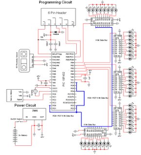
Personal Radar
source of this information is http://www.pyroelectro.com/
- Part 1: Introduction of Personal Radar System based on PIC18f452
- Part 2: Parts List of Radar system
- Part 3: Circuit diagram and Schematic of PIC Radar
- Part 4: Theory of Operation of IR Radar
- Part 5: Hardware and the functionality of different components
- Part 6: Software routines and implementation
- Part 7: Data and Observations
- Part 8: Conclusion
For more detail: contruction of personal Radar System using PIC MIcrocontroller PIC18f452
- What are the main components used in this project?
The project uses three main devices: an IR Range sensor, a PIC microcontroller PIC18f452, and an LED array display. - How does the system measure distance?
The system measures close proximity at an angle of 90 degrees using an IR sensor. - What is the operating range of the radar system?
The range is roughly 4-30cm, 20-150cm, or 1m-5.5m depending on the sensor chosen. - Can I use different sensors for different ranges?
Yes, the range varies from 4-30cm up to 5.5m depending on which sensor you choose to use. - What voltage regulator is required for the circuit?
An LM7805 5v Voltage Regulator is listed as a necessary electrical part. - How many LEDs are used to display the output?
The design utilizes 36x LEDs to display the output of the radar system. - What type of oscillator is needed for the microcontroller?
A 4 or 8 MHz Oscillator is required for the circuit operation. - Does the project require latches for the display?
Yes, the parts list includes 5x 74LS373 Latches.