If anyone having any problem at any point, ask in comments and I will try my best to resolve them. So, let’s get started with Interfacing of LCD with PIC Microcontroller.
Circuit Designing in Proteus
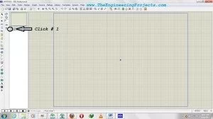
- First of all, open the Proteus ISIS software.
- In the start, it will look exactly the same as in below image.
- Now click on button P as shown in below figure.
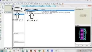
- When you click this button a new window will pop up as shown in below figure.
- This is the place where we search our components, like as I want 7805 so I searched for this component and the Proteus has given me the related components.
- Once you get your desired component, simply double click on it and it will be added in your database so that you can use them.
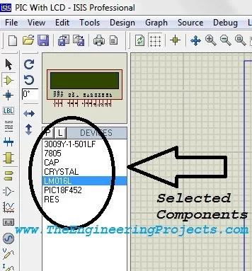
- The below image shows the components which we are gonna use in this project, so simply search for all the components and then double click on them and finally you will get all the components as shown below:
- Now place these components in the Proteus workspace and connect them.
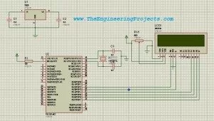
- Design exactly the same circuit as shown in the below figure for interfacing of LCD with PIC Microcontroller.
- Now our circuit in Proteus is ready to use, the next step is to write a code for the PIC Microcontroller 18F452 and then burn it into the Proteus and check its working.
Code of LCD with PIC18F452
- There are different compilers to write the code for PIC Microcontroller. Here I am using MikroC Pro for PIC. You can get it easily from the official site of MikroC.
- I am not going in the details of coding as its beyond the scope of this tutorial, but still I am posting the code.
- So now create a new project in the MikroC Pro For PIC and copy the below code and paste it in the project and compile.
- When you compile the project, it will create a .hex file in the same folder where you have saved this project. We will use this hex file shortly.
LCD module connections
sbit LCD_RS at RD2_bit;
sbit LCD_EN at RD3_bit;
sbit LCD_D4 at RD4_bit;
sbit LCD_D5 at RD5_bit;
sbit LCD_D6 at RD6_bit;
sbit LCD_D7 at RD7_bit;
sbit LCD_RS_Direction at TRISD2_bit;
sbit LCD_EN_Direction at TRISD3_bit;
sbit LCD_D4_Direction at TRISD4_bit;
sbit LCD_D5_Direction at TRISD5_bit;
sbit LCD_D6_Direction at TRISD6_bit;
sbit LCD_D7_Direction at TRISD7_bit;
// End LCD module connections
char txt1[] = “www.TheEngineeri”;
char txt2[] = “ngProjects.com”;
char i; // Loop variable
void Move_Delay() { // Function used for text moving
Delay_ms(500); // You can change the moving speed here
}
void main(){
Lcd_Init(); // Initialize LCD
Lcd_Cmd(_LCD_CURSOR_OFF); // LCD Cursor Off
Lcd_Cmd(_LCD_CLEAR); // Clear display
Lcd_Out(1,1,txt1); // Write text in first row
Lcd_Out(2,1,txt2); // Write text in second row
Delay_ms(2000);
while(1);
}
Burn the Code in PIC Microcontroller in Proteus ISIS
- Now we have the hex file, we need to burn this hex file in the microcontroller in Proteus.
- So, double click on the Microcontroller in Proteus and it will open up the properties menu of PIC microcontroller.
- Now click, as shown in the below figure, and browse for the hex file and click OK.
- We need to add this hex file in Proteus here and also select the oscillation frequency which I have selected 16MHz.
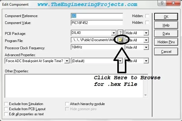
Note: Make sure that the oscillation frequency remain same both in the MikroC and the Proteus.
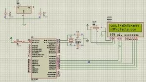
- After adding the file in the Proteus now click OK and play the simulation, ifeverything goes fine, you will get the results as shown in below image.
Note:
- Proteus ISIS simulation file and the .hex file has been emailed to all the subscribed members. If anyone need it, subscribe to our newsletter via email and it will be emailed to you as well.
That’s all for today, I have tried my best to explain everything on Interfacing of LCD with PIC Microcontroller, but still if someone having problem ask in comments and I will try to resolve. In the next part, we will discuss various components of Proteus which are commonly used like motors, serial port, hyper terminal etc. So stay tuned and also subscribe us via email so that you get all the tutorials straight into your mail box. Have fun. Take care.