
Summary of PIC12F1822 ADC and PWM modules
The article explains how to configure and use the 10-bit ADC and ECCP PWM modules on the PIC12F1822 microcontroller using the CCS PIC C compiler. It details setting up analog input pins, selecting channels, reading values, and calculating PWM frequency via Timer2 configuration.
Parts used in the PIC12F1822 Microcontroller Project:
- PIC12F1822 microcontroller
- Analog potentiometer
- Analog temperature sensor
- CCS PIC C compiler
This topic gives a short descriptions about PIC12F1822 microcontroller ADC and PWM module and how to use them using CCS PIC C compiler. For more details go to PIC12F1822 datasheet.
PIC12F1822 ADC Module:
PIC12F1822 microcontroller has a 10-bit ADC (Analog-to Digital Converter) module. 4 Pins can be used as analog inputs which are: RA0 (AN0), RA1 (AN1) RA2 (AN2) a,d RA4 (AN3).
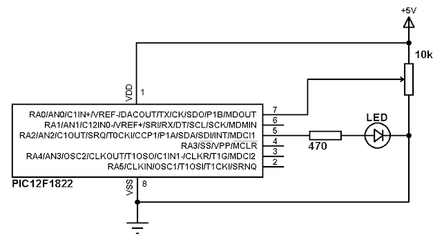
The ADC module is used to read analog data comes from analog devices like analog potentiometer and analog temperature sensors ……
The ADC converts analog data into 10-bit digital data which is stored into the ADC result registers (ADRESH:ADRESL register pair).
The following CCS C line is used to configure PIC12F1822 ADC module:
setup_adc(int16 mode);
Where mode is the source of the conversion clock (ADC clock source). There
are seven possible clock options:
• FOSC/2
• FOSC/4
• FOSC/8
• FOSC/16
• FOSC/32
• FOSC/64
• FRC (dedicated internal oscillator)
CCS PIC C compiler uses the following constants for the previous parameters (used with setup_adc():
ADC_CLOCK_DIV_2
ADC_CLOCK_DIV_4
ADC_CLOCK_DIV_8
ADC_CLOCK_DIV_32
ADC_CLOCK_DIV_16
ADC_CLOCK_DIV_64
ADC_CLOCK_INTERNAL
And to turn off the ADC use the following constant:
ADC_OFF
Example:
setup_adc(ADC_CLOCK_DIV_4);
The following line is used to configure a digital pin as analog:
setup_adc_ports();
The following constants are used in the previous function:
sAN0 // Configure AN0 as analog
sAN1 // Configure AN0 as analog
sAN2 // Configure AN0 as analog
sAN3 // Configure AN0 as analog
NO_ANALOGS // All pins are configured as digital
ALL_ANALOGS // All pins are configured as analog
Example:
setup_adc_ports(sAN1); // Configure AN1 as analog
setup_adc_ports(sAN0 | sAN3); // Configure AN0 and AN3 as analog
To read analog data the analog channel must be selected first using this line:
set_adc_channel(int8 channel);
Where channel can be: 0, 1, 2 or 3.
Example:
set_adc_channel(2); // Select analog channel 2
And to read data use the following line:
read_adc();
PIC12F1822 PWM module:
PIC12F1822 microcontroller has 1 ECCP module (Enhanced Capture/Compare/PWM) which allows us to generate Pulse-Width Modulation (PWM) signals.
The PWM period is specified by the PR2 register of Timer2. The PWM period can be calculated using the following equation:
PWM period = [(PR2) + 1] • 4 • Tosc • (TMR2 Prescale Value)
And the PWM frequency is defined as 1/[PWM period].
PR2 is Timer2 preload value,
Tosc = 1/(MCU_frequency)
TMR2 Prescale Value can be 1, 4, 16 or 64.
For example forPR2 = 255 , microcontroller frequency = 8MHz and Prescale = 16 we get a PWM frequency of 488Hz.
The CCS Timer2 configuration has the following form:
setup_timer_2(mode, period, postscale);
where: mode is TMR2 Prescale Value, period is PR2 and postscaler is not used in the determination of the PWM frequency (keep it 1).
Previous example gives the following Timer2 configuration command:
setup_timer_2(T2_DIV_BY_16, 255, 1);
The PWM resolution determines the number of available duty cycles for a given period. For example, a 10-bit resolution will result in 1024 discrete duty cycles, whereas an 8-bit resolution will result in 256 discrete duty cycles.
Read more: PIC12F1822 ADC and PWM modules
- Which pins can be used as analog inputs?
RA0, RA1, RA2, and RA4. - How do you configure the ADC clock source?
Use the setup_adc function with constants like ADC_CLOCK_DIV_4 or ADC_CLOCK_INTERNAL. - What is the command to read analog data?
The read_adc() function is used to retrieve the converted digital value. - How is the PWM period calculated?
It is determined by the equation [(PR2) + 1] • 4 • Tosc • (TMR2 Prescale Value). - What are the available TMR2 prescale values?
The values can be 1, 4, 16, or 64. - How do you select a specific analog channel?
Use the set_adc_channel function with a number between 0 and 3. - What determines the PWM resolution?
Resolution defines the number of discrete duty cycles available for a given period. - How do you turn off the ADC module?
Use the constant ADC_OFF within the setup_adc function.
