Summary of Chapter 1: PIC16F887 Microcontroller – Device Overview
The PIC16F887 is a versatile, low-cost Microchip RISC microcontroller with 35 instructions, single-cycle execution (except branches), and up to 20 MHz operation. It offers a precision internal oscillator, 2.0–5.5V supply, low-power modes, 8K flash, 256-byte EEPROM, 368-byte RAM, 14-channel 10-bit ADC, timers, watchdog, comparators with Vref, PWM, enhanced USART, MSSP (SPI/I2C), and 35 multifunction I/O pins with in-circuit serial programming.
Parts used in the PIC16F887 Microcontroller Overview:
- PIC16F887 microcontroller (PDIP 40 package)
- Internal precision oscillator (factory calibrated)
- Quartz crystal oscillator (optional for up to 20 MHz)
- Power supply (2.0–5.5V)
- Brown-out Reset (BOR) circuitry
- Power-Saving Sleep Mode circuitry
- In-Circuit Serial Programming (ICSP) interface
- 8K Flash memory
- 256-byte EEPROM
- 368-byte RAM
- 14-channel 10-bit A/D converter
- Three timers/counters
- Watchdog timer
- Two analog comparators with fixed and programmable voltage reference
- PWM output steering control
- Enhanced USART module (supports RS-485, RS-232, LIN2.0, Auto-Baud Detect)
- Master Synchronous Serial Port (MSSP) supporting SPI and I2C
- 35 multifunction I/O pins (with high current source/sink, pull-ups, Interrupt-on-Change)
The PIC16F887 is one of the latest products from Microchip. It features all the components which modern microcontrollers normally have. For its low price, wide range of application, high quality and easy availability, it is an ideal solution in applications such as: the control of different processes in industry, machine control devices, measurement of different values etc. Some of its main features are listed below.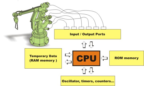
- RISC architecture
- Only 35 instructions to learn
- All single-cycle instructions except branches
- Operating frequency 0-20 MHz
- Precision internal oscillator
- Factory calibrated
- Software selectable frequency range of 8MHz to 31KHz
- Power supply voltage 2.0-5.5V
- Consumption: 220uA (2.0V, 4MHz), 11uA (2.0 V, 32 KHz) 50nA (stand-by mode)
- Power-Saving Sleep Mode
- Brown-out Reset (BOR) with software control option
- 35 input/output pins
- High current source/sink for direct LED drive
- software and individually programmable pull-up resistor
- Interrupt-on-Change pin
- 8K ROM memory in FLASH technology
- Chip can be reprogrammed up to 100.000 times
- In-Circuit Serial Programming Option
- Chip can be programmed even embedded in the target device
- 256 bytes EEPROM memory
- Data can be written more than 1.000.000 times
- 368 bytes RAM memory
- A/D converter:
- 14-channels
- 10-bit resolution
- 3 independent timers/counters
- Watch-dog timer
- Analogue comparator module with
- Two analogue comparators
- Fixed voltage reference (0.6V)
- Programmable on-chip voltage reference
- PWM output steering control
- Enhanced USART module
- Supports RS-485, RS-232 and LIN2.0
- Auto-Baud Detect
- Master Synchronous Serial Port (MSSP)
- supports SPI and I2C mode
Pin Description
As seen in Fig. 1-1 above, the most pins are multi-functional. For example, designator RA3/AN3/Vref+/C1IN+ for the fifth pin specifies the following functions:
- RA3 Port A third digital input/output
- AN3 Third analog input
- Vref+ Positive voltage reference
- C1IN+ Comparator C1positive input
This small trick is often used because it makes the microcontroller package more compact without affecting its functionality. These various pin functions cannot be used simultaneously, but can be changed at any point during operation.
The following tables, refer to the PDIP 40 microcontroller.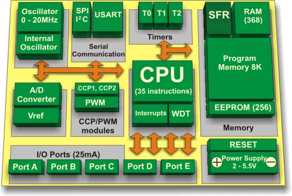
Central Processor Unit (CPU)
I’m not going to bore you with the operation of the CPU at this stage, however it is important to state that the CPU is manufactured with in RISC technology an important factor when deciding which microprocessor to use.
RISC Reduced Instruction Set Computer, gives the PIC16F887 two great advantages:
- The CPU can recognizes only 35 simple instructions (In order to program some other microcontrollers it is necessary to know more than 200 instructions by heart).
- The execution time is the same for all instructions except two and lasts 4 clock cycles (oscillator frequency is stabilized by a quartz crystal). The Jump and Branch instructions execution time is 2 clock cycles. It means that if the microcontroller’s operating speed is 20MHz, execution time of each instruc tion will be 200nS, i.e. the program will be executed at the speed of 5 million instructions per second!
For more detail: Chapter 1: PIC16F887 Microcontroller – Device Overview
- What is the instruction set size of the PIC16F887?
The PIC16F887 uses a RISC architecture with only 35 instructions. - How fast does the PIC16F887 execute instructions?
All single-cycle instructions execute in 4 clock cycles except Jump and Branch which execute in 2 clock cycles. - What operating frequency does the PIC16F887 support?
The PIC16F887 supports 0–20 MHz operation and has a precision internal oscillator. - What are the memory capacities of the PIC16F887?
It has 8K Flash ROM, 256 bytes EEPROM, and 368 bytes RAM. - How many ADC channels and what resolution does it have?
It includes a 14-channel A/D converter with 10-bit resolution. - Does the PIC16F887 support serial communication protocols?
Yes; it has an enhanced USART (supports RS-485, RS-232, LIN2.0) and an MSSP that supports SPI and I2C. - Can the PIC16F887 be programmed in-circuit?
Yes; it supports In-Circuit Serial Programming allowing programming while embedded in the target device. - What power-saving features does the PIC16F887 offer?
It offers Power-Saving Sleep Mode and low consumption modes (e.g., 50nA standby). - How many I/O pins are available and what special I/O features exist?
It has 35 I/O pins with high current source/sink, individually programmable pull-ups, and Interrupt-on-Change capability.