Summary of CAT BOT
The Cat Bot project creates a robot that follows a cat toy using ultrasonic sensors. It employs two PIC32 microcontrollers: a Big board for the robot and a Little board for the toy. The system uses high-pass filters, op-amps, and rectifiers to process weak 40kHz signals. Software includes an ISR for calibration, motor control threads, and a TFT display showing the cat's eyes moving with direction.
Parts used in the Cat Bot:
- PIC32 microcontroller (Big board)
- PIC32 microcontroller (Little board)
- Ultrasonic sensors (TR-89 transducers)
- TFT screen
- L293D H-bridge
- 4N35 opto isolators
- AA batteries
- Resistors (100Ω, 330Ω, 430Ω, 33kΩ, 22kΩ, 10kΩ, 100kΩ)
- Capacitors (10nF, 1nF, 2nF)
- Diodes (1N4001)
- Op-Amp circuit components
- On-board LED
Introduction
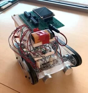
Cat Bot, as its name suggests, is a cat robot that sees and follows around a cat toy, simulating actions of real cats. We have decided on this project since this system involves significant hardware and software elements, and constructing it required us to bring in a variety of knowledge gained through the previous labs over the course of this semester. Developing methodologies to orchestrate such a system highlighted the hardware-software co-design philosophy, a core aspect of this course. In the end, we have successfully constructed a robot that followed our expectations, but with much more sophisticated hardware requirements than we had anticipated.
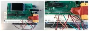
The Cat Bot project is implemented using Sean Caroll’s Big board and Little board, each equipped with PIC32 microcontrollers. The Big board was used to control the robot and process data read from two ultrasonic sensors. It was responsible for decoding the sensor readings and appropriately setting the variables that control the motion of the robot and the face being displayed on the TFT screen. The Little board was used to create a sound emitting circuit with two additional ultrasonic sensors. Pulse-width modulation methodology was employed to control the motor’s speed as well as the rate of signal being transmitted through the cat toy. The signal sent out by the cat toy would get detected and translated to control the robot. Once turned on, the robot would first calibrate itself to the environment and then it would signal that it is ready to start listening to the cat toy by turning on its on-board LED. If no signal was detected, the robot would stay in place. Otherwise, it would execute one of the three directional movements: move straight, turn left, or turn right. To explicitly display the state of the robot, the cat face displayed on the TFT screen would look in the direction of the robot’s motion.
High-Level Design
Rationale Behind The Project
When students leave home to attend classes at their designated university, they often leave their pets at home. For many people, their pet is a stress reliever and offers much joy in life. For our project we decided to develop a pet robot that could act as a substitute for one’s pet while they are living away from home.
We knew that the ECE 4760 final project was going to be an intense couple of weeks of development, and we wanted to enjoy every second of the design process. As a group we decided to develop a product that required a high level of human-robot interaction throughout the development process. The pet robot was one of our initial ideas and it satisfied our project requirements. There are existing robots on the market currently being advertised to children, however because of their high cost and unnatural interactions with humans, no specific pet robot model has yet taken off. We knew that as time progressed we would be able to learn and grow with our creation, even if other models already exist, and possibly develop a prototype that would be cheaper and more enjoyable than available models.
The idea of a robot that would be able to detect and follow a specific object was adopted from ECE 3400 but we attempted to make a robot that would act more like a real cat, using frequencies above the human hearing range to guide the robot instead of visible light. Before we began the creation process we wanted to make sure our idea was feasible. With experience gained from ECE 3400 we knew that sensors could detect the approximate location of an object. This ment with a right set of sensors we could make the pet robot play fetch or follow an object, only this time the sensors would be a lot more complicated to work with.
Background Math
To process the signal received from the two ultrasonic sensors on the frame of the robot, several techniques were utilized including filtering, amplification, and software calibration of the signals. Below are some of the details of these components.
High-Pass Filter
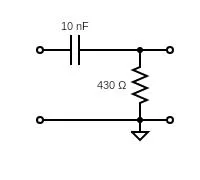
To get rid of an unwanted DC signal as described in the Design section below, we implemented a high-pass filter with a cutoff frequency of just below the target 40kHz at which the sensors operate. The cutoff frequency for a high-pass filter is given by the formula 1/2πRC. For our application, since we wanted to let the 40kHz frequency through but remove any low frequency noise, we ended up choosing C = 10nF and R = 430Ω to get a resulting cutoff frequency of around 37kHz. Since there were no 430Ω resistors available, we simply put a 100Ω and a 330Ω resistor in series.
Non-Inverting Op-Amp
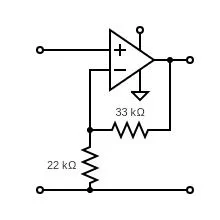
As one of the steps in the signal processing circuit described in the Design section below, we implemented an operational amplifier circuit to increase the sensor output reading by a factor of approximately 2.5 as given by the equation Vout / Vin = 1 + R1 / R2. Using 33kΩ for R1 and 22kΩ for R2, we successfully implemented an amplifying circuit.
Voltage Representation of ADC Values
Knowing that the board operates at 3.3V, we can obtain the voltage value of the integer ADC values by multiplying by 3.3 and dividing by 1023. This calculation was derived once we have realized that there exists a difference in the sensitivity of each sensor we have mounted on the robot. More detail of the use of such conversion is to follow in the Software section of the report, in particular under the description for Interrupt Service Routine (ISR).
Logical Structure
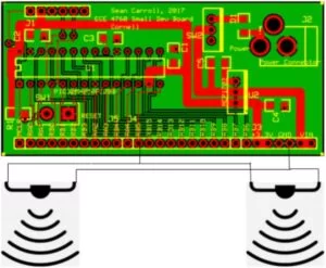
The cat robot consists of multiple levels of custom circuitry in order to operate the motors for movement and ultrasonic sensors for object detection. Another separate circuit was also mounted on a wooden block with a stick that is used as a cat toy to guide the robot in the direction of the incoming sound. The brains of the robot and cat toy are two PIC32 microcontrollers which generate PWM signals to control either the robot’s motors or the cat toys’ ultrasonic transducers.
In order to accurately determine the location of the cat toy, on-board ultrasonic receivers were installed on the cat robot. Many levels of amplification, rectification, and filtering were added to produce a clean DC signal to be input into the PIC32’s ADC. The firmware then processed the analog signal to accurately determine the robot’s next direction based on where the cat toy is located.
Hardware / Software Tradeoffs
Since a critical part of the project was the robot’s ability to detect ultrasonic waves and make calculations based on the received signals, it was important to make sure that a strong enough signal was received and that the signals given out by the left and right sensors on the robot were similar in magnitude. This proved to be somewhat difficult since the sensors we used were old and varied greatly in their ability to detect sound. This often meant the one sensor was weaker than the other during the signal detection process. We tried our best to calibrate the sensors by making changes to the signal processing circuit such as changing the values of the resistors and capacitors, however, a lot of calibration was still needed to be done in software. After processing the signal through hardware, most of the initial meaning was stripped away. The circuitry added delays and voltage drops that we couldn’t account for, meaning creating code to accurately determine the location of the cat toy became increasingly difficult.
Another hardware pitfall was PIC32’s inability to generate perfectly sinusoidal waveforms at 40kHz. As previously mentioned, the cat toy included two ultrasonic transducers that needed to emit a sound wave at approximately 40kHz. PIC32 connected to the ultrasonic transducers would generate a PWM signal that oscillated at 40kHz in order to be picked up by the cat bot. This signal, however, was not perfectly compatible with TR-89 transducers since these devices operated with a sinusoidal signal and the small board did not have the capability to produce smooth oscillating waves, only square signals.
Finally, the cat toy’s PIC32 only operated on 3.3 volts, meaning its peak PWM signal could only reach the maximum operating voltage. The function generators that were used during initial testing of the sensors were able to provide stronger ultrasonic signals at higher voltage levels. The lower peak voltage level of the PWM signal posed a difficulty since this signal could only be detected at close range. The circuitry needed to solve this problem proved to be too difficult to develop within the given timeframe.
Relationship of This Design to Available IEEE, ISO, ANSI, DIN, and Other Standards
While we are using an ultrasonic sensor to detect an object, most standards only account for industrial grade sensors used in metal and drone testing.
Existing Patents, Copyrights, and Trademarks Which are Relevant to This Project
Currently there are many cat robots out on the market, each with many different uses. Some are for cats, and others are for children. A current design called the mars cat is one of many examples of robot cats. This means there is room in the market for new ideas.
Hardware
Hardware Overview
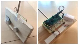
The Cat Bot was created using a simple robot chassis with treads on both sides, to allow for the most optimum turning capability. Three levels of custom circuitry were created with the sole purpose of providing movement and sensing capabilities to the robot. The bottom level was designed specifically to operate the motors used to move the robotic cat. The middle level provided sensing capabilities through the circuitry designed to operate analog ultrasonic sensors. The top level included the PIC32 prototype board in order to control the bottom two levels and connect both custom circuits.
First Level
The circuitry designed for the first level of the cat robot was designed to control two on-board motors, which would allow the device to move in any direction specified by the user. Since the motors operate on a simple 6V DC connection, the L293D h-bridge was chosen to control the rotational direction of each mechanism. The IC is able to direct current through each motor connected to its output ports, however, in order to control the rotational speed, PWM signals need to be sent to each input port on the L293D. Since the motor controller is directly connected to the motors, circuitry needed to be added to account for any microcontroller damage that is due to directly connecting PWM signals from the PIC to the L293D. Four opto isolator circuits using 4N35 ICs were added to help protect the PIC from being directly connected to the motor circuit.
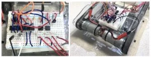
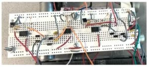
In order to power the bottom level, a power source that could directly activate each motor was needed. Four AA batteries were attached to the bottom of the chassis to provide a little more than 6V to the circuit. The 6V power line was also passed through a 5V regulator in order to provide the correct voltage level to activate the internal logic in the L293D. A completed diagram of the motor circuit as well as its physical implementation are displayed in the figure below.
Second Level
After first testing the TR-89 sensors we realized that even with one of the transducers connected to the function generator operating at around 9V, the signal received by the other transducer is very small, with maximum amplitudes around 5-10mV. This signal would not be strong enough for the ADC to pick up and would not provide us with a large enough range of ADC units to perform calculations on. Additionally, the received signal also varied in time just like the signal that was output by the sound emitting device. In order for the ADC to produce constant readings that are proportional to the distance from the robot to the cat toy, the ADC needed a DC signal as an input and not a wave. Therefore, the main objective of the signal processing circuit on the second level of the robot frame is to amplify and rectify the signal received by the left and right ultrasonic sensors, while also reducing noise and making the signal as stable as possible for the ADC to read.
To amplify the signal, our first instinct was to just pass it through a non-inverting op-amp circuit. While this attempt did technically amplify the signal, the circuit did also add some undesired elements to the signal such as a slight DC offset and a change to the shape of the signal. To combat this, we did more research on circuit designs that are specific to our application. Using a preamplifier circuit described in here, we build an analogous circuit with slightly different resistor and capacitor values that would be more applicable to our sensors. The signal is amplified using an op-amp powered by the PIC32 with a gain of approximately R2 / R1 = 100kΩ / 10kΩ = 10. As previously stated, the sensors were highly variable in their quality, however with the implementation of the circuit shown in Figure X below, the maximum amplitude of the signal received by the sensors was amplified to approximately 500 mV. This circuit also serves to reduce possible noise and echo signals through the use of two diodes connected in parallel. In our circuit, we chose to use two 1N4001 diodes. After passing through the circuit above, the signal was amplified significantly and without a noticeable change to its shape, unlike after passing through the originally attempted op-amp circuit. However, we did run into the issue of the sensor output continuously accumulating a constant voltage offset as time ran on.
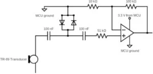
If the transducer was held near a sound source for some period of time, it would eventually gain a significant DC offset that would make evaluating the distance between the sensors inaccurate. To remove this offset we built a passive high-pass filter using C=10 nF and R=430Ω with a cutoff frequency of 37kHz. After implementing the filter, the amplitude of the received signal was successfully amplified but without the additional DC offset. The last step to making the signal more readable for the ADC was then to convert it to a DC signal using a rectifier circuit.
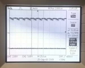
Since even the amplified signal wasn’t very strong, we first attempted to build a half-wave rectifier circuit with a Schottky diode. The output of the circuit was as expected, however, it wasn’t smoothed out enough for our application. Channel 1 of the oscilloscope in Figure X below shows the output waveform from the half-wave rectifier circuit. While it does look a lot more constant than the pure amplified output from the filter, the signal was not close enough to DC in the 25s time period which was how often the signal would be sampled by the ADC.
In an attempt to smooth out the amplified signal as much as possible, we build a full-wave bridge rectifier circuit with capacitors. Four 1N4001 diodes were used for the bridge and two 1nF capacitors were connected in parallel. For the left sensor, we ended up switching one of the 1nF capacitors for a 2nF capacitor to stabilize the sensor reading a bit more. With a smaller value for the capacitor, the DC reading for the left sensor would decay too fast in comparison to that for the right sensor as the cat toy was moved away. Since it is important for later calculations for the readings to be as similar as possible, we had to pay close attention to the decay time for each sensor.
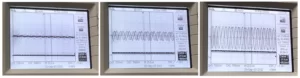
The input and output of the full wave bridge rectifier circuit for three different distances between the sensors are shown in figure X above. Channel 1 of the oscillascope shows the amplified signal that passed through the high-pass filter and channel 2 shows the same signal after passing through the rectifier circuit. In the 25s time frame, the output signal was almost perfectly constant so it could easily be read by the ADC and produce relatively stable readings for a given distance between the sound emitting and sound receiving sensors.
The ADC takes in voltages in the range of 0 to 3.3V and converts it to ADC units in the range of 0 to 1023. To make the ADC output as high as possible, we implemented a second amplifying circuit with the rectifier output as an input to the op-amp. We build a non-inverting op-amp circuit with a gain of 1 + 33kΩ / 22kΩ = 2.5. This was enough to produce ADC readings of around 800-900 ADC units at very close distances between emitting and receiving sensors. The full signal processing circuit diagram, as well as its physical implementation for both the right and left sensors are shown in figure X below.
Third Level
The final level of the structure included a PIC32 Big board which would be connected to the initial two levels creating one circuit. Four PWM signals were activated on the microcontroller to control the first level motor circuit. These ports included RA4, RB9, RB0, and RB7 which used Output Compare modules 1-4. The second level was connected to two designated ADC ports on the PIC32, these included pins RB3 and RB13. The sensors would send signals to the PIC’s ADC ports, which in turn would set the PWM signals to move the motors in the desired direction. More logic of the motion decision is to follow in the Software section. Also, the 3.3V of the microprocessor was used to power the second level circuit so that the reference ground is consistent with the sensors. Because this level only served as a data communication hub, no external hardwares were necessary.
Cat Toy
In addition to the robot frame, the Cat Bot also required its cat toy circuit to be implemented. Because we have tested the TR-89 sensors with relatively high output voltages from the function generator, we thought of implementing another amplifier circuit for the PWM signal from the Little Board to raise its amplitude from a maximum of 3.3V to around 9V. However, due to this amplifying circuit being difficult to implement due to the high frequency of the PWM signal, we decided to not amplify the signal and just work with the Cat Bot at closer distances.
Also, to be able to precisely control the direction of Cat Bot’s motion, we originally had three ultrasonic sensors connected together on the cat toy, however these sensors turned out to be extremely directional and for a sensor to pick up any sound it had to be directly facing the other sensor. Hence, the final circuit of the Little Board was simply composed of the PIC connecting two ultrasonic sensors through one PWM signal.
Software
In a big picture, there are two software scripts that orchestrate the entire project: one for the robot and one for the cat toy. Because the cat toy only needed to emit PWM signals, the software logic was trivial to implement. Also, because the underlying software interface was the same as the Big board, the process of using different functions was also similar to how we would have implemented it using the Big board. However, the Little board had its own header files that had slight modifications from the Big board. More description is to follow in the following sections.
The basic software design idea for the robot was adapted from the ECE 3400 light-following-robot project (Spring 2021). Translated for PIC32, the robot’s code is composed of 4 main components: ISR, motor control thread, catface thread, and a main function. The ISR was responsible for controlling ADC values and communicating with the motor control thread to make the robot move in the direction of interest. The catface thread was simply responsible for printing out the face of the cat in the TFT display for us to explicitly see the changes in its direction. The main, as with any other code, was responsible for setting up different hardware peripheral controls and initializing variables. For the complete picture of the code, refer to Appendix C.
Interrupt Service Routine (ISR)
The ISR was responsible for reading 2 ADC values and communicating what the right “state” that the robot should be in. The “state” of the robot describes whether the robot should stay in place, go straight, turn left, or turn right. More description is to follow in the Motor Control Thread section. The ISR used Timer 2 to establish a constant 1000 clock cycle interrupt that would read ADC values at 40kHz. The two ADC values were read using “ReadADC(0)” and “ReadADC(1)”. The ADC readings come from the sensor readings that get passed through the circuit described above in the Hardware section.
Before we passed the values into the logic that interacts with the motors, we first needed to go through some calibration steps. Under ambient conditions, the ultrasonic sensors may catch some noise values that would offset the actual readings from the ultrasonic emitter (i.e., cat toy). Hence, we needed to first dedicate a few ISR cycles to accumulate the ambient ADC reading data and derive the approximate ambient noise that exists in the environment. By averaging the accumulated value, we would be able to get an estimate of the ambient noise, which we can subtract from future readings to remove any effects due to noise. We have selected to have it run for 4000 ISR cycles since that gave us about a second or two in real time, which provided us with sufficient time to sample the data and safely assume that the robot has calibrated its sensor readings to the ambient condition. To signal that the calibration was done, we made the on-board LED to toggle on.
The raw values of ADC readings are fine. However, having to work only with raw ADC values would be difficult and we would have to be very precise about our measurements. Hence, we had to derive some additional metrics from ADC readings. First, we casted the _Accum data type of ADC readings to an integer type. Doing so gave us a value with resolution of 0 to 1023, which enabled us to get a better grasp of how the ADC values actually change with reasonable numerical values. But recall that we are subtracting the ambient readings from the actual readings, which may cause the actual readings to go below 0. To address this issue, we have reassigned the value to 1 in case subtracting the ambient value is larger than the actual reading. The next metric derived from ADC values were normalized measurements (NM). The normalized measurements are defined by the fraction of each sensor reading over the sum of total ADC values. This gave us an insight of the ratio of how much “proportion of signals” is received by each transceiver sensor. Since the NM values for each sensor will sum to 1 (hence the normalized keyword), we can compare the NM values of each ADC readings and determine which direction the robot should move by picking the one that has the greater value. To determine which side has the greater value, we used the percentage of the differences between two NM measurements. With threshold set to 50%, the NM makes the robot turn left if the value is greater than 50% (i.e., the left sensor gets more proportion of signal with respect to the right) and makes the robot turn right if the value is less than -50% (i.e., the left sensor gets more proportion of signal with respect to the right). The fact that the comparison has to be made using negative proportion is because the NM difference does not look at the absolute difference but the actual numerical difference between the left and right NM measurements.

Notice that previously, we have set the integer ADC readings to 1 in case it goes below 0 after ambient readings have been subtracted. This is precisely because setting them to 0 would incur a division-by-zero error when we calculate the normalized measurements. Finally, to control the state discrimination logic more precisely, we calculated the respective voltage values of ADC readings. This new metric was added as an auxiliary logic that puts more constraints in logic that enables (going staring and turning left) since they were more sensitive to sensor readings than (turning right) logic. Because the Big board operates with 3.3V, we multiplied the value by 3.3 and divided by 1023 to scale the ADC readings to the voltage range.
Once all the metrics are calculated, we pass them through multiple different conditional statements to determine what “state” the robot should be in. If it were to be the case that both sensors detect a certain level of signals, then it would go straight. Otherwise, depending on the integer readings of ADC values, the robot will turn right, turn left, or stay still. Note that the normalized measurement differences are used in each logic to determine whether the detected signal is valid or not. The normalized measurement difference was useful since it gave us how “significant” the signal is to each sensor (i.e., whether the difference is significant to conclude as input signals). Different threshold values were determined through trial-and-error methodology. After it has appropriately set the “state” variable, it would set the flag variable “reading_ready” to high to tell the motor control thread that the value is ready and gets ready to read another ADC signal.
Motor Control Thread
The motor control thread was used to configure different PWM signals that were inputted to the H-bridge. Because the state of the robot depends on the ADC readings, the motor control thread yields until the ISR calibrates ADC readings and configures the motor state appropriately using the logic mentioned above. Once it recognizes that the computations are done, it decodes the “state” variable that the ISR has set. We have configured the motor states the following way:
- 0: Go straight
- 1: Turn left
- 2: Turn right
- 3: Cannot be determined (stop)
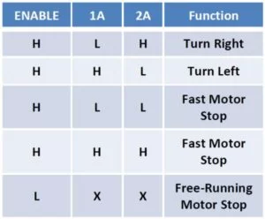
For each different state, we configured the value that each of the 4 output compare modules received following the Bidirectional DC Motor Control table specified in the H-bridge datasheet shown below. Because we wanted to have a consistent movement speed, we kept the same duty cycle in places where a high signal was required as an input.
Towards the end, we put a buffer of 0.5 seconds to prevent motor states from changing too rapidly. Had we omitted the buffer, the fast-changing motor state values due to ADC readings would have overloaded the control signals being sent to the motors, which would not be ideal for the hardware.
Catface Thread
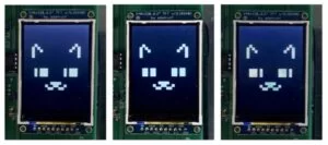
As the Cat Bot would need to display its state explicitly, we implemented a thread that would be dedicated to printing out the robot’s face depending on the direction of its motion. Because the TFT screen is relatively high in resolution, we modeled the screen as pixels of width 10. Doing so allowed us to look at the TFT screen as a larger picture and thus making it easy to figure out which pixels needed to be highlighted to express the face of the cat. We first drafted the face outline in an excel sheet and later translated it to the code by manually translating the pixel values. Using the “tft_gfx” header file, we were able to use multiple instances of “tft_fillRect” functionality to draw out the cat face. Like the Biods lab, the screen was first cleared to remove any remaining instance of pixels from the screen. Then, the thread would first draw the ears of the cat, fill in the eyes, and finally draw the mouth.
To reflect the changes of robot state, we expanded the logic for drawing the eyes of the Cat Bot. If it were to be the case that the robot is staying still or going straight, it would print irises in the middle of its eyes. However, if the robot was turning left, the iris will shift to the left side of the eye. The similar logic applies to the motion of turning right. This was easily implemented by shifting the pixels dedicated for the iris to the left and right depending on the direction of its rotation. With expanded logic for the eyes, we were able to not only make it more visually appealing but also make it easier to detect and debug issues relating to the inconsistency between the expected behavior and the actual calculated behavior. Due to the amount of projections necessary, we decided to print every 0.5 seconds to ensure that all pixels are being displayed in a sufficient amount of time.
Main
As with most of the conventional programs, the main function serves as initializing different hardware peripheral settings and initializing different variables. It opens up Timer 2, sets up 2 ADC ports, opens up 4 output compare modules, sets up onboard LED, initializes ambient calculation variables, and schedules the threads. Most of the software implementations were similar to previous labs we have done in class. Indeed, different from previous labs where we only used 1 output compare module, we had to open up 4 output compare modules to support the control logic of L293D H-bridge logic for our motors. However, following the Peripheral Pin Select (PPS) output table, we were able to easily scale up the numbers and configure them appropriately to make the robot move. The biggest difference is that we had to enable 2 ADC ports instead of just one. To do so, we followed the sample code. It first enables ADC sampling with different setup parameters (more details in the commented code in Appendix C) similar to previous projects that have used ADC ports. However, to make sure that two ports are selected, we disabled the scanning ability of all the ports other than analog pins we have selected to ensure that no ADC readings happen from different ports. The two analog pins we have used as the ADC values were AN5 and AN11 ports, each corresponding to RB3 and RB13 pins on the board, respectively. We have selected them by carefully considering which ports each output compare module supports, specified by the Peripheral Pin Select (PPS) output table.
Compared to the Big board script, the Little board script for our cat toy had a much simpler objective. The ISR would simply clear the interrupt flag and the dedicated thread for the PWM would configure the output compare channel to the specific PWM value so that the signal can be sent. In the main, the output compare module is opened along with Timer 2 to allow for the PWM signal to be transmitted. One caveat in designing the script for the little board was the difference in operating frequency between the Big board and the Little board. Because the system operates at 40MHz and we want to emit a 40kHz signal for the communication between the robot and the cat toy, the interrupt time of the clock was set to 1000 clock cycles. Hence, this made us set the interrupt count of Timer 2 to 1000 and set the duty cycle to be calculated with respect to 1000. The complete picture of the Little board code can also be found here.
During the developmental phase, one software issue we have confronted was that one of the ADC ports we have configured was unable to display any values. We verified that there were no pin conflicts in the software and yet the port was still not working. This led us to initially believe that there were issues with the hardware. But later we realized that the configured pin was not suited for reading the ADC values so we had to find another pin that was functional. Had we noticed this earlier on, we would not have had to invest time in trying to debug hardwares that had been working without any errors. Hence, for those who wish to conduct a similar experiment with ADC ports, we would advise you to check the functionality of the pins using 3.3V and ground pins of the board first to see if the values are indeed functional before connecting to any hardware peripherals.
Results
Demo video
At the end, we were able to successfully demonstrate the Cat Bot following the signal that was being output by the cat toy. Even though the robot’s actions were not as clear-cut as we had anticipated them to be, the robot satisfyingly demonstrated behavior in accordance with the cat toy’s motion. Despite many challenges such as low and uneven signals received from the ultrasonic sensors, we were able to come up with a hardware circuit and software calibration to mitigate the effects of these unexpected behaviors (such as weak communication signals) as much as possible.
Throughout the development of the robot, we relied on oscilloscope data to debug virtually every circuit we built since the use of this tool made it easier to isolate errors whenever there could be many bugs present, both in the software and the hardware components. Additionally, we used the TFT to print out various data values such as the real-time ADC readings for the left and the right sensors. Doing so allowed us to devise various threshold values via trial-and-error methods. We could also observe how these values changed over time and what additional calibration might have been needed.
Even though the Cat Bot was able to perform needed tasks, there is still a lot of room for improvement. One change that would make the robot better would be the use of a better ultrasonic sensor, or possibly another long range technology that doesn’t involve dealing with high frequency signals, for example infrared sensors. When operating under lower voltages that could be provided by the microcontroller, the sensors had to be brought into very close proximity to the sound source to be able to pick up even the smallest signal. As seen from snippets of the video, the cat toy had to be brought very close to the robot for it to react accordingly. Sometimes, the toy had to be physically touching the sensors for the robot to move.
Speed of Execution & Accuracy
In this application, accuracy is most importantly determined by the abilities of the sensors to detect sound waves that may be present, and not necessarily by the sampling rate of the ADC. Since the ADC runs on Timer 2 which uses a 40kHz frequency, this sampling rate is our limit. However, the sensor readings are gathered very quickly, much quicker than the robot can react to them, so the system is not very limited by the speed of the ADC. Also, we have been dealing with different representations of ADC values with different types. We have first casted the raw ADC readings to an integer value and used that information to calculate voltage measurement and the normalized measurement. Hence, the accuracy of our data being used would mainly depend on int and float data types. Because we did not use the raw readings of ADC, the accuracy of our calculation would not depend on the _Accum data type.
Safety
The Cat Bot project involves communication using high-frequency signals, however, the 40kHz at which the sensors communicate is far above the audible range so it should have minimal effects on the user of the Cat Bot.
Interface & Usability
The Cat Bot has a very simple user interface. It utilizes the on-board LED to signal the user that the robot is ready to start taking in inputs from the user. The cat toy has a long enough handle that enables users to use the toy without having to bend over to control the robot. Moreover, the facial expression displayed on the TFT screen allows the user to easily interact with the robot by looking at the dynamic changes happening in the display. Such a simple interface of Cat Bot allows users to easily operate and play around with it.
As a result of TR-89’s poor sensing abilities, the cat toy had to be within less than a centimeter from the sensors. This wasn’t hard to achieve whenever we tested the robot off the floor, however, as we began testing the robot for the demo we realized that it is extremely difficult to physically keep the cat toy so close to the robot without touching the sensors. Whenever the sound source would touch the sensor, the signal received by the left and right sensors would stay at the same high level for a long period of time, which sometimes led to inaccurate reactions from the robot. This was one of the biggest problems in the usability of our design, however, with better ultrasonic transducers and a longer sensing range this issue can be reduced.
Conclusion
After spending many hours designing and constructing a pet robot, we were able to successfully create a robot that follows a signal. It was able to correctly respond to signals that come from the left, right, and straight and act accordingly with a certain level of accuracy. While we were able to develop the system from start to finish, our end product was very different from our initial proposal. Our original goal was to create a dogbot, with the capability of following its owner and playing fetch at a much greater distance than our current one. We had planned on not only enabling it to follow from afar but also have the ability to play fetch using the same ultrasonic sensor communication. However, our initial proposal proved to be too challenging with the sensors at our disposal.
The ultrasonic sensors proved to be inadequate in detecting objects at distances greater than 1cm. This raised an alert in our project timeline and caused us to devise an alternative plan as soon as possible. We still wanted to create a pet robot, so we changed our idea to be a cat that would follow a toy instead of a dog that could play fetch.
In the end, we decided to modify our design such that only the task of “following the signal” can be achieved with a little help from the user, since the sensors were inadequate for their designated purpose. Learning from experience, we would need to invest more time doing research ahead of time on sensors in our next project opportunity. We believe that sampling different sensors with the similar capabilities as ultrasonic sensors and supporting communication of distances greater than one meter with great accuracy before starting to assemble the circuit would benefit our next design journey. Most of the time spent in the lab involved debugging our second level circuitry to allow the ADC to detect the ultrasonic sensor’s signal and having known the functional capabilities of the sensor would have greatly shortened the process.
But, despite the semi-drastic divergence from our original plan, we were able to create a system that contains three levels of analog circuitry with different software calibrations done to fine-tune the parameters. We believe that this project really highlights the importance of hardware-software co-development.
Applicable Standards
Most standards deal with industrial grade ultrasonic sensors in regards to non destructive testing. Our sensors were only tested with low power levels, so the possibility of creating a destructive sound wave was impossible. Otherwise no other standards were applicable to our final project.
Intellectual Property Considerations
We believe that we do not have any issues with intellectual property considerations. Even though we adopted the general idea from past projects of ECE 3400, only the high level idea was brought in and we have explicitly mentioned about the use of such ideas previously. Additionally, most of the code structure and hardware implementations were created from scratch. In case we referenced publicised work, we made sure that we provide clear citations to such properties (preamplifier circuit, for instance). We do not plan to patent or publish our project in any shape or form.
Ethical Considerations
Throughout the project every group member was able to treat their colleagues and other groups with respect in accordance to the IEEE Code of Ethics. Before using any dangerous tool or testing circuitry, we made sure to make safety our number one priority. As a group we were able to overcome any conflicts with respect and without any violence.
Safety and Legal Considerations
Even though the embedded circuitry and the physical body of the project may be complex, there are no major safety or legal considerations that need to be addressed. There is no opportunity for the Cat Bot and a cat toy to incur a physical disturbance. One potential source we had to check was the use of ultrasonic transceivers that establish the connection between the Cat Bot and the cat toy with a 40kHz frequency signal. However, since the operating signal is in the band of 9kHz – 45kHz limit that is allocated for any transmitter use specified by FCC Part 15 rules, we believe there are no legal considerations that have to be made about our system.
Overall, we believe that the Cat Bot project was a successful demonstration of hardware-software co-development that highlights the importance of a robotic system development. The project provided an interesting playground for us to explore different hardware and come up with solutions to fix any system-wide problems we have encountered, abiding to ethical and legal restrictions, throughout the developmental process.
Appendix C – Commented Code
/*
  *  ECE 4760 Fall 2021 Final Project
  *  Authors: YoungSeok Na, Arina Ignatova, Alexander Scotte
  */

  //========================================================================
  // Prelude
  //========================================================================
  // clock AND protoThreads configure!
  // You MUST check this file!
  #include "config_1_3_2.h"
  // threading library
  #include "pt_cornell_1_3_2.h"

  // graphics libraries
  #include "tft_master.h"
  #include "tft_gfx.h"
  // need for rand function
  #include
  #include

  //========================================================================
  // Global Variables
  //========================================================================
  // string buffer
  char buffer[60];

  // Output compare trigger rate.
  int generate_period = 40000;

  // PWM duty cycle control.
  int pwm_on_time;

  //== Timer 2 interrupt handler ===========================================
  volatile SpiChannel spiChn = SPI_CHANNEL2 ;	// the SPI channel to use
  volatile int spiClkDiv = 4 ; // 10 MHz max speed for port expander!!

  // Normalized measurement threshold for determining direction.
  float threshold;

  // Activation signals for motors.
  volatile int motor_state, reading_ready;

  // Raw readings of ADC.
  volatile _Accum sense_left, sense_right;

  // Integer-casted ADC reading.
  volatile int left_reading, right_reading;

  // Accumulators for ambient condition calibration.
  volatile int left_sum, right_sum, left_ambient, right_ambient;

  // Counter for ambient condition calibration time.
  volatile int ambient_setup;

  // Normalized measurements of ADC values.
  volatile float nm_left, nm_right, diff;

  // Voltage values of ADC values.
  volatile float volt_left, volt_right, volt_diff;

  //========================================================================
  // ISR
  //========================================================================
  // 1kHz control rate
  void __ISR(_TIMER_2_VECTOR, ipl2) Timer2Handler(void)
  {
      //--------------------------------------------------------------------
      // ADC
      //--------------------------------------------------------------------
      // Example from TFT_ADC_READ_SCAN
      // https://people.ece.cornell.edu/land/courses/ece4760/PIC32/Target_board/version_1_3_2/TFT_ADC_read_SCAN.c
      sense_left = ReadADC10(0);  // AN5
      sense_right = ReadADC10(1); // AN11

      // Convert to int
      left_reading = (int) sense_left;
      right_reading = (int) sense_right;

      // Calculate their respective voltage value.
      volt_left = left_reading * ( 3.3 / 1023 );
      volt_right = right_reading * ( 3.3 / 1023 );

      // If, under the ambient condition, the readings are too extreme,
      // bring them down (ex: reading of 50+ for ambient)
      if ( ambient_setup < 4000 ) {
          if ( ambient_setup == 3999 ) {
              // Ambient readings = average of all the readings so far.
              left_ambient = left_sum / 4000;
              right_ambient = right_sum / 4000;

              // Toggle on-board LED to signal that the ambient calibration is done.
              mPORTAToggleBits(BIT_0);
          }
          else {
              left_sum += left_reading;
              right_sum += right_reading;
          }
          ambient_setup++;
          reading_ready = 0;
      }
      else {
          // Calibration - subtract ambient readings to normalize.
          left_reading -= left_ambient;
          right_reading -= right_ambient;

          //
          if ( left_reading < 0 ) {
              left_reading = 1;
          }
          if ( right_reading < 0 ) {
              right_reading = 1;
          }

          // Calibration for right sensor - picked up more noise than left one.
          if ( (right_reading > 10) && (right_reading < 40) ) {
              right_reading %= 10;
          }

          // Cap the reading to avoid extreme accumulation of ADC values.
          if ( left_reading > 400 ) {
              left_reading = 400;
          }

          if ( right_reading > 400 ) {
              right_reading = 400;
          }

          // Calculate the normalized measurement
          nm_left = (float) left_reading / (float) ( left_reading + right_reading );
          nm_right = 1 - nm_left;
          diff = (nm_left - nm_right) * 100;

          // Calculate voltage difference.
          volt_diff = abs(volt_left - volt_right);

          // Determine the motor state based on various conditions.
          // * 0: Go straight
          // * 1: Turn left
          // * 2: Turn right
          // * 3: Cannot be determined (stop)
          if ( ( left_reading > 40 ) && ( right_reading > 40 ) && (volt_diff < 0.2) ) {
              if ( abs(diff) > threshold ) {
                  motor_state = 3;
              }
              else {
                  motor_state = 0;
              }
          }
          else if ( (left_reading > 40) && (volt_diff > 0.25)) {
              if ( diff < threshold ) {
                  motor_state = 3;
              }
              else {
                  motor_state = 1;
              }
          }
          else if ( right_reading > 40 ) {
              if ( diff > -threshold ) {
                  motor_state = 3;
              }
              else {
                  motor_state = 2;
              }
          }
          else {
              motor_state = 3;
          }

          // Signal the motor thread to change configuration
          reading_ready = 1;
      }

      // Ready to read again
      AcquireADC10();

      // Clear the timer interrupt flag
      mT2ClearIntFlag();
  }

  //========================================================================
  // Motor control thread
  //========================================================================
  // Depending on the ADC readings, normalized measurements, and voltage
  // values, determine whether the robot should turn left, turn right, or
  // go straight.
  // If nothing can be detected, stay in place.
  static PT_THREAD (protothread_hbridge(struct pt *pt))
  {
      static int begin_time, i;
      PT_BEGIN(pt);
      while(1) {
          // Yield until the ADC value is ready.
          PT_YIELD_UNTIL(pt, reading_ready == 1);
          reading_ready = 0;

          // Go straight
          if ( motor_state == 0 ) {
              SetDCOC1PWM(pwm_on_time);
              SetDCOC2PWM(0);
              SetDCOC3PWM(0);
              SetDCOC4PWM(pwm_on_time);

          }
          // Turn left
          else if ( motor_state == 1 ) {
              SetDCOC1PWM(pwm_on_time);
              SetDCOC2PWM(0);
              SetDCOC3PWM(pwm_on_time);
              SetDCOC4PWM(0);
          }
          // Turn right
          else if ( motor_state == 2 ) {
              SetDCOC1PWM(0);
              SetDCOC2PWM(pwm_on_time);
              SetDCOC3PWM(0);
              SetDCOC4PWM(pwm_on_time);
          }
          // Cannot determine - Stay in place.
          else {
              SetDCOC1PWM(0);
              SetDCOC2PWM(0);
              SetDCOC3PWM(0);
              SetDCOC4PWM(0);
          }
          begin_time = PT_GET_TIME();
          while ( PT_GET_TIME() - begin_time < 500 );
      }
      PT_END(pt);
  }
  //========================================================================
  // Catface Thread
  //========================================================================
  // Print the catface that displays the state of the cat.
  static PT_THREAD (protothread_catface(struct pt *pt))
  {
      PT_BEGIN(pt);
      while(1) {
          // yield time 0.5 second
          PT_YIELD_TIME_msec(500);

          // Clear the screen
          tft_fillRoundRect(0, 0, 239, 319, 1, ILI9340_BLACK);

          //           x, y,  w,   h, color
          // Ears
          tft_fillRect(30, 80, 10, 40, ILI9340_WHITE);
          tft_fillRect(40, 70, 10, 10, ILI9340_WHITE);
          tft_fillRect(50, 80, 10, 10, ILI9340_WHITE);
          tft_fillRect(60, 90, 10, 10, ILI9340_WHITE);

          tft_fillRect(170, 90, 10, 10, ILI9340_WHITE);
          tft_fillRect(180, 80, 10, 10, ILI9340_WHITE);
          tft_fillRect(190, 70, 10, 10, ILI9340_WHITE);
          tft_fillRect(200, 80, 10, 40, ILI9340_WHITE);

          // Eyes
          if ( motor_state == 0 || motor_state == 3 ) {
              // Looking straight
              tft_fillRect(40, 160, 10, 30, ILI9340_WHITE);
              tft_fillRect(50, 160, 10, 30, ILI9340_WHITE);
              tft_fillRect(70, 160, 10, 30, ILI9340_WHITE);
              tft_fillRect(80, 160, 10, 30, ILI9340_WHITE);

              tft_fillRect(150, 160, 10, 30, ILI9340_WHITE);
              tft_fillRect(160, 160, 10, 30, ILI9340_WHITE);
              tft_fillRect(180, 160, 10, 30, ILI9340_WHITE);
              tft_fillRect(190, 160, 10, 30, ILI9340_WHITE);
          }
          else if ( motor_state == 1 ) {
              // Looking Left
              tft_fillRect(40, 160, 10, 30, ILI9340_WHITE);
              tft_fillRect(60, 160, 10, 30, ILI9340_WHITE);
              tft_fillRect(70, 160, 10, 30, ILI9340_WHITE);
              tft_fillRect(80, 160, 10, 30, ILI9340_WHITE);

              tft_fillRect(150, 160, 10, 30, ILI9340_WHITE);
              tft_fillRect(170, 160, 10, 30, ILI9340_WHITE);
              tft_fillRect(180, 160, 10, 30, ILI9340_WHITE);
              tft_fillRect(190, 160, 10, 30, ILI9340_WHITE);
          }
          else {
              // Looking right
              tft_fillRect(40, 160, 10, 30, ILI9340_WHITE);
              tft_fillRect(50, 160, 10, 30, ILI9340_WHITE);
              tft_fillRect(60, 160, 10, 30, ILI9340_WHITE);
              tft_fillRect(80, 160, 10, 30, ILI9340_WHITE);

              tft_fillRect(150, 160, 10, 30, ILI9340_WHITE);
              tft_fillRect(160, 160, 10, 30, ILI9340_WHITE);
              tft_fillRect(170, 160, 10, 30, ILI9340_WHITE);
              tft_fillRect(190, 160, 10, 30, ILI9340_WHITE);
          }

          // Mouth
          tft_fillRect(80, 220, 10, 10, ILI9340_WHITE);
          tft_fillRect(90, 230, 20, 10, ILI9340_WHITE);
          tft_fillRect(100, 210, 40, 10, ILI9340_WHITE);
          tft_fillRect(110, 220, 20, 10, ILI9340_WHITE);
          tft_fillRect(130, 230, 20, 10, ILI9340_WHITE);
          tft_fillRect(150, 220, 10, 10, ILI9340_WHITE);
      }
      PT_END(pt);
  }

  //========================================================================
  // Main
  //========================================================================
  void main( void ) {
      //--------------------------------------------------------------------
      // General
      //--------------------------------------------------------------------
      // Config threads - turns OFF UART support and debugger pin, unless
      //                  defines are set
      PT_setup();

      // Setup system wide interrupts
      INTEnableSystemMultiVectoredInt();

      //--------------------------------------------------------------------
      // DAC setup timer interrupt
      //--------------------------------------------------------------------
      // Set up timer2 on,  interrupts, internal clock, prescalar 1, toggle
      // rate at 40 MHz PB clock
      // 40,000,000/Fs = 909 : since timer is zero-based, set to 908
      OpenTimer2(T2_ON | T2_SOURCE_INT | T2_PS_1_1, 40000);

      // set up the timer interrupt with a priority of 2
      ConfigIntTimer2(T2_INT_ON | T2_INT_PRIOR_2);
      mT2ClearIntFlag(); // and clear the interrupt flag

      // Divide Fpb by 2, configure the I/O ports. Not using SS in this example
      // 16 bit transfer CKP=1 CKE=1
      // possibles SPI_OPEN_CKP_HIGH;   SPI_OPEN_SMP_END;  SPI_OPEN_CKE_REV
      // For any given peripherial, you will need to match these
      // clk divider set to 4 for 10 MHz
      SpiChnOpen(SPI_CHANNEL2, SPI_OPEN_ON | SPI_OPEN_MODE16 | SPI_OPEN_MSTEN | SPI_OPEN_CKE_REV , 4);
      // end DAC setup

      //--------------------------------------------------------------------
      // ADC setup
      //--------------------------------------------------------------------
      // configure and enable the ADC
      // 2 ADC ports --> 1 for each sensor
      CloseADC10(); // ensure the ADC is off before setting the configuration

      // define setup parameters for OpenADC10
      // Turn module on | ouput in integer | trigger mode auto | enable autosample
      // ADC_CLK_AUTO -- Internal counter ends sampling and starts conversion (Auto convert)
      // ADC_AUTO_SAMPLING_ON -- Sampling begins immediately after last conversion completes; SAMP bit is automatically set
      // ADC_AUTO_SAMPLING_OFF -- Sampling begins with AcquireADC10();
      #define PARAM1 ADC_FORMAT_INTG16 | ADC_CLK_AUTO | ADC_AUTO_SAMPLING_ON

      // define setup parameters for OpenADC10
      // ADC ref external  | disable offset test | disable scan mode | do 1 sample | use single buf | alternate mode off
      #define PARAM2  ADC_VREF_AVDD_AVSS | ADC_OFFSET_CAL_DISABLE | ADC_SCAN_ON | ADC_SAMPLES_PER_INT_2 | ADC_ALT_BUF_OFF | ADC_ALT_INPUT_OFF

      // Define setup parameters for OpenADC10
      // use peripherial bus clock | set sample time | set ADC clock divider
      // ADC_CONV_CLK_Tcy2 means divide CLK_PB by 2 (max speed)
      // ADC_SAMPLE_TIME_5 seems to work with a source resistance < 1kohm
      #define PARAM3 ADC_CONV_CLK_PB | ADC_SAMPLE_TIME_15 | ADC_CONV_CLK_Tcy

      // define setup parameters for OpenADC10
      // AN5 and AN11 as signals
      #define PARAM4 ENABLE_AN5_ANA | ENABLE_AN11_ANA

      // define setup parameters for OpenADC10
      // do not assign channels to scan
      #define PARAM5 SKIP_SCAN_AN0 | SKIP_SCAN_AN1 | SKIP_SCAN_AN2 | SKIP_SCAN_AN3 | SKIP_SCAN_AN4 | SKIP_SCAN_AN6 | SKIP_SCAN_AN7 | \
        SKIP_SCAN_AN8 | SKIP_SCAN_AN9 | SKIP_SCAN_AN10 | SKIP_SCAN_AN12 | SKIP_SCAN_AN13 | SKIP_SCAN_AN14 | SKIP_SCAN_AN15

      // Use ground as neg ref for A
      SetChanADC10( ADC_CH0_NEG_SAMPLEA_NVREF );
      OpenADC10( PARAM1, PARAM2, PARAM3, PARAM4, PARAM5 ); // configure ADC using the parameters defined above

      EnableADC10(); // Enable the ADC

      //--------------------------------------------------------------------
      // Config output compare modules (PWM)
      //--------------------------------------------------------------------
      // Set up compare modules for double compare mode
      // - First number is the time to clear, second is the time to set the pin
      // - In this case, the end of the timer period and 50% of the timer period

      // 1 & 2 for left motor
      // OC1 is PPS group 1, map to RPB7 (pin 16)
      // OC2 is PPS group 2, map to RPB8 (pin 17)
      OpenOC1(OC_ON | OC_TIMER2_SRC | OC_PWM_FAULT_PIN_DISABLE , generate_period-1, 0);
      PPSOutput(1, RPB7, OC1);

      OpenOC2(OC_ON | OC_TIMER2_SRC | OC_PWM_FAULT_PIN_DISABLE , generate_period-1, 0);
      PPSOutput(2, RPB8, OC2);

      // 3 & 4 for right motor
      // OC3 is PPS group 4, map to RPB9 (pin 18)
      // OC4 is PPS group 3, map to RPB13 (pin 24)
      OpenOC3(OC_ON | OC_TIMER2_SRC | OC_PWM_FAULT_PIN_DISABLE , generate_period-1, 0);
      PPSOutput(4, RPB9, OC3);

      OpenOC4(OC_ON | OC_TIMER2_SRC | OC_PWM_FAULT_PIN_DISABLE , generate_period-1, 0);
      PPSOutput(3, RPA4, OC4);

      //--------------------------------------------------------------------
      // Digital output enables (H-bridge)
      //--------------------------------------------------------------------
      // init the display
      tft_init_hw();
      tft_begin();
      tft_fillScreen(ILI9340_BLACK);
      //240x320 vertical display
      tft_setRotation(0); // Use tft_setRotation(1) for 320x240

      // seed random color
      srand(1);

      //--------------------------------------------------------------------
      // Variable initialization
      //--------------------------------------------------------------------
      // LED to signal whether the robot is ready to be acted upon RF signals
      mPORTASetPinsDigitalOut(BIT_0); // Set port as output
      mPORTAClearBits(BIT_0);

      motor_state = 0;
      pwm_on_time = 33000;
      threshold = 50;

      // Determine ambient NM
      ambient_setup = 0;
      left_sum = 0;
      right_sum = 0;
      left_ambient = 0;
      right_ambient = 0;

      //--------------------------------------------------------------------
      // Initialize protothreads
      //--------------------------------------------------------------------
      PT_setup();
      pt_add(protothread_catface, 0); // To be deleted later
      pt_add(protothread_hbridge, 0);
      PT_INIT(&pt_sched);
      pt_sched_method = SCHED_ROUND_ROBIN;

      // round-robin scheduler for threads
      PT_SCHEDULE(protothread_sched(&pt_sched));
  }
Little board (cat toy) code (open in text)
  //========================================================================
  // Prelude
  //========================================================================
  // clock AND protoThreads configure!
  // You MUST check this file!
  #include "config.h"
  // threading library
  #include "pt_cornell_1_2_1.h"

  //========================================================================
  // Global Variables
  //========================================================================
  int generate_period = 40000;
  static struct pt pt_wrist;

  void __ISR(_TIMER_2_VECTOR, ipl2) Timer2Handler(void)
  {
      mT2ClearIntFlag();
  }
  //========================================================================
  // PWM Thread
  //========================================================================
  // Send specified PWM signal to RB5
  static PT_THREAD (protothread_wrist(struct pt *pt))
  {
      static int pwm_on_time;
      PT_BEGIN(pt);
      pwm_on_time = 500;
      while(1) {
          SetDCOC2PWM(pwm_on_time);
      }
      PT_END(pt);
  }

  //========================================================================
  // Main
  //========================================================================
  void main(void) {
      //SYSTEMConfigPerformance(PBCLK);

      ANSELA = 0; ANSELB = 0;

      // === config threads ==========
      // turns OFF UART support and debugger pin, unless defines are set
      PT_setup();

      // === setup system wide interrupts  ========
      INTEnableSystemMultiVectoredInt();

      OpenTimer2(T2_ON | T2_SOURCE_INT | T2_PS_1_1, 1000);

      // set up the timer interrupt with a priority of 2
      ConfigIntTimer2(T2_INT_ON | T2_INT_PRIOR_2);
      mT2ClearIntFlag(); // and clear the interrupt flag

      OpenOC2(OC_ON | OC_TIMER2_SRC | OC_PWM_FAULT_PIN_DISABLE , 500, 0);
      PPSOutput(2, RPB5, OC2);

      PT_INIT(&pt_wrist);
      // round-robin scheduler for threads
      while(1) {
          PT_SCHEDULE(protothread_wrist(&pt_wrist));
      }
  }
Appendix D – Schematics
Cat Bot Complete Circuit
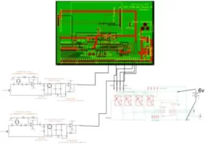
Source: CAT BOT
- How does the robot determine which direction to move?
The robot calculates normalized measurements from left and right sensor readings; if the left value is greater than 50%, it turns left, and if less than -50%, it turns right. - What frequency do the ultrasonic sensors operate at?
The sensors communicate using a 40kHz signal frequency. - Can the robot detect the cat toy from a long distance?
No, the sensors are inadequate for distances greater than 1cm, requiring the toy to be very close or touching the sensors. - Does the robot use visible light to follow the toy?
No, the robot uses frequencies above the human hearing range via ultrasonic sensors instead of visible light. - What component protects the microcontroller from motor circuit damage?
Four opto isolator circuits using 4N35 ICs were added to protect the PIC from direct connection to the motor circuit. - How does the robot indicate it is ready to start?
The robot turns on its on-board LED after calibrating itself to the environment. - What happens if no signal is detected by the sensors?
If no signal is detected, the robot stays in place. - Why was a high-pass filter implemented in the circuit?
A high-pass filter was used to remove unwanted DC signals and low-frequency noise while allowing the 40kHz frequency to pass.