


Summary of Building the PIC16F84 based game system
This article guides users in assembling a PIC16F84 based game system, emphasizing soldering techniques like mounting low-profile components first to avoid heat damage. It details the sequential installation of resistors, diodes, sockets, capacitors, and headers on a single-sided PCB.Parts used in the PIC16F84 Based Game System:
- 15 resistors (11 x 1k, 1 x 470, 1 x 2k7, 1 x 10k, 1 x 220)
- Diode
- 18pin socket
- Two 100nF capacitors
- Reset switch
- 1k potentiometer
- Two 5x100k resistor networks
- Two 22pF capacitors
- Two 3.3uF capacitors
- 6 pin angled programming header
This text describes how to build my PIC16F84 based game system, before you start you should read through the whole text one time. Note that many components are sensitive to too much heat and will get damaged if you heat them too much when soldering. The drawn placement images show components to mount in each step in black and the components mounted in previous steps in gray.
When soldering the components onto the PCB it is easier if you can put the PCB with the components side flat down, so you should solder components of the same height at the same time. To be able to add components of different height you'll need to start with the lowest first and build your way up.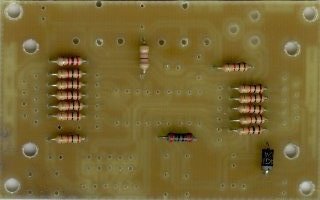
Resistors
The first thing to mount when adding components to a single sided PCB is the wire bridges because they are the lowest "components", but this board doesn't have any wire bridges so we can start with the resistors.
Add the 15 resistors (11 x 1k, 1 x 470, 1 x 2k7, 1 x 10k, 1 x 220) and the diode. Note that the diode is polarized and should be mounted with the cathode (marked with a line) closest to the edge of the PCB.
Location of the 15 resistors and the diode. (Click to enlarge)
Socket and SIL resistor networks.
The next step is to add the 18pin socket, the two 100nF capacitors (if they are of the same height as the sockets), the reset switch, the 1k potentiometer and the two 5x100k resistor networks.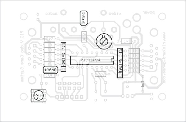 Note that the resistor networks are polarized with their common pin marked with a dot or a line that should point at the same direction as the diode as seen in the pictures here to the right.
Low capacitors
The two 22pF, the two 3.3uF capacitors and the 6 pin angled programming header should be mounted next. The 3.3uF capacitors are polarized and should have their minus-side mounted closest to the edge of the board.
For more detail: Building the PIC16F84 based game system
- How should I handle components during soldering?
Many components are sensitive to too much heat and will get damaged if you heat them too much when soldering. - What is the best way to arrange components by height?
You need to start with the lowest first and build your way up to add components of different heights. - Which components should be mounted first on this board?
You can start with the resistors because this board does not have any wire bridges. - How do I identify the correct orientation for the diode?
The diode is polarized and should be mounted with the cathode closest to the edge of the PCB. - How are the resistor networks oriented?
The common pin marked with a dot or line should point at the same direction as the diode. - Which capacitors are polarized and how should they be placed?
The two 3.3uF capacitors are polarized and should have their minus-side mounted closest to the edge of the board. - Can I mount capacitors and sockets together?
You can add the two 100nF capacitors along with the 18pin socket if they are of the same height.
Related projects
PIC Stepper Motor Controller using PIC16F84A with Proteus Simulation
Introduction Stepper motors are widely used in embedded systems and DIY electronics projects where precise position control is required. This PIC Stepper...
Programmers & ICSP · PIC16F84APIC Musical Doorbell using PIC16F84A with Proteus Simulation
IntroductionThis microcontroller project demonstrates a musical doorbell built around a PIC16F84A and a simple piezo sounder.Using two push buttons, the system allows...
Beginner Tutorials · PIC16C84Exploring the World of PIC Microcontrollers: An Architectural Overview
A Peripheral Interface Microcontroller (PIC), developed by General Instruments Microcontrollers in 1993, operates under software control and is programmed to execute various...
Games, Toys & CalculatorsExploring Leon’s Mini Random Number Generator (mRNG)
Sales Pitch Feeling overwhelmed by choices? Who isn't? Decision-making can be a maze. White, rye, or wheat? Pinstripes or polka dots? Feast...
Games, Toys & Calculators · PIC16F628ATIC TAC TOE game using PIC16F628
This project is not to introduce Tic Tac Toe. Everyone knows this game. It's to introduce two features. Bi-coloured LEDs, microcontrollers and...
Games, Toys & CalculatorsInteractive Blitz Chess: A Physical Blitz Chess Board Powered with PIC32
Introduction We created a companion system for physical chess boards to help players enjoy their fast paced blitz game with a chess...

Ibrar Ayyub
I am an experienced technical writer holding a Master's degree in computer science from BZU Multan, Pakistan University. With a background spanning various industries, particularly in home automation and engineering, I have honed my skills in crafting clear and concise content. Proficient in leveraging infographics and diagrams, I strive to simplify complex concepts for readers. My strength lies in thorough...