Summary of Building a 3-channel, high power RGB LED driver
This article describes a DIY 3-channel RGB LED driver built using the PT4115 chipset to learn PCB design. The circuit allows independent PWM control for each channel via headers, supporting input voltages up to 30V and driving high-power LEDs (3W, 10W, or 20W). Current is regulated by selecting specific sense resistors; for instance, a 0.33-ohm resistor yields approximately 300mA per channel.
Parts used in the 3-channel RGB LED Driver:
- PT4115 chipset
- Sense resistor (e.g., 0.33 ohm)
- Male/female headers (for PWM control)
- PCB board
- High power LEDs (3W/10W/20W)
- Arduino (as an example controller)
Hey guys,
I built another board, which is a 3-channel (RGB) LED driver based on an inexpensive chipset called PT4115 (you can find them on eBay or Aliexpress).
The circuit is very simple and looks like Sparkfun’s PicoBuck. However, I used beefier components and a different chip. You may say it’s pretty much the same thing, but I made it to learn some more about PCB design.
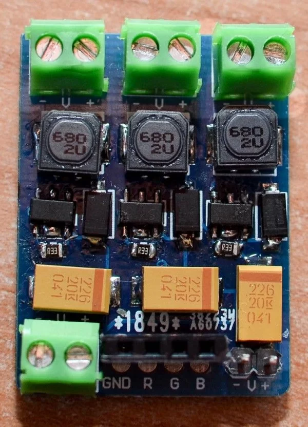
Datasheet here. LED current is set through a sense resistor. The output current I is equal to 0.1/Rs. I wanted ~300mA for each channel so I chose a 0.33 ohm resistor. If you want 350mA, choose a 0.27ohm resistor.
Each channel can be controlled via PWM (you can solder male/female headers on the board), for example with an Arduino.
You can input up to 30V and control 3W/10W/20W LEDs.
For more detail: Building a 3-channel, high power RGB LED driver
-
How is the output current determined?
The output current I equals 0.1 divided by the sense resistor value (Rs). -
What resistor value is needed for 300mA per channel?
A 0.33 ohm resistor should be chosen to achieve approximately 300mA. -
Which resistor value sets the current to 350mA?
You should choose a 0.27 ohm resistor for 350mA. -
Can the channels be controlled via PWM?
Yes, each channel can be controlled via PWM by soldering male/female headers on the board. -
What is the maximum input voltage supported?
The driver accepts an input of up to 30V. -
What power levels of LEDs can this driver control?
It can control 3W, 10W, or 20W LEDs. -
Is an Arduino required to operate the driver?
No, but an Arduino is mentioned as an example device that can use the soldered headers for PWM control. -
Where can the PT4115 chipset be purchased?
The chipset can be found on eBay or Aliexpress.