AN857 Sensorless Brushless DC Motor Control using PIC16F877 with Proteus Simulation

Summary of AN857 Sensorless Brushless DC Motor Control using PIC16F877 with Proteus Simulation


This project implements sensorless BLDC motor control on a PIC16F877, using BEMF sampling instead of Hall sensors. It demonstrates closed-loop speed control, six-step commutation, PWM modulation, and automatic acceleration/deceleration, and is fully testable in Proteus VSM. Firmware uses Timer0, Timer1, ADC, and CCP modules with lookup tables for timing and commutation; BEMF is sampled at 1/4T and 3/4T and compared to half the supply voltage to adjust speed.

Parts used in the AN857 Sensorless BLDC Motor Control Project:

  • PIC16F877 microcontroller
  • 3-phase Brushless DC motor (BLDC)
  • Potentiometers (two: PWM control and offset)
  • Resistors (voltage dividers and pull-ups)
  • Capacitors (ADC filtering and decoupling)
  • Crystal oscillator (20 MHz)
  • Proteus VSM simulation components
  • External power drivers and protection circuitry (for higher-power implementations)

Introduction

This microcontroller project demonstrates sensorless brushless DC (BLDC) motor control using a PIC16F877 microcontroller, based on Microchip’s AN857 application note.
The design removes the need for Hall sensors by intelligently measuring back electromotive force (BEMF) during motor operation.
Using Proteus simulation, the project shows how closed-loop speed control, PWM modulation, and automatic acceleration/deceleration can be implemented in real time.
It’s a strong example of practical embedded systems design, combining analog sensing, timers, ADCs, and precise firmware control.
This project is ideal for learning motor control fundamentals using a classic PIC microcontroller.

Sensorless BLDC motor control setup
Illustrative View of the Concept.

How the Project Works (Overview)

The system controls a three-phase BLDC motor in a sensorless closed-loop configuration.
Two potentiometers are used: one sets the base PWM and speed reference, while the other applies a PWM offset for fine adjustment.
Instead of position sensors, the firmware measures BEMF on the floating motor phase at specific points in the commutation cycle.
The measured BEMF is compared against half of the supply voltage to determine whether the motor speed should increase, decrease, or remain stable.
All timing, commutation, and speed correction logic is handled by the PIC16F877 using Timer0, Timer1, ADC, and CCP modules.

Block Diagram / Workflow Explanation

  1. PWM & Speed Input
    Potentiometers connected to AN0 and AN1 set PWM duty cycle and RPM reference.

  2. Motor Commutation
    Timer1 and CCP module trigger six-step BLDC commutation using lookup tables.

  3. Supply Voltage Sampling
    During Phase 4, the system samples the applied motor voltage to establish a reference.

  4. BEMF Detection
    During Phase 5, BEMF is sampled at ¼T and ¾T of the phase period.

  5. Speed Decision Logic
    BEMF values are compared to Vsupply/2 to determine acceleration, deceleration, or locked speed.

  6. Closed-Loop Adjustment
    RPM index and timer presets are adjusted automatically or manually depending on operating mode.

Key Features (Auto-Derived)

  • Sensorless BLDC motor control using BEMF detection

  • Closed-loop speed control with automatic acceleration and deceleration

  • Six-step commutation using lookup tables

  • PWM-based voltage and speed control

  • Dual-potentiometer manual and automatic speed adjustment

  • Real-time BEMF sampling synchronized to PWM cycles

  • Timer-based phase control using CCP special event triggers

  • Fully testable in Proteus VSM environment

Components Used

  • PIC16F877 microcontroller

  • Brushless DC motor (3-phase)

  • Potentiometers (PWM control and offset)

  • Resistors (voltage dividers and pull-ups)

  • Capacitors (ADC filtering and decoupling)

  • Crystal oscillator (20 MHz)

  • Proteus VSM simulation components

Applications

  • BLDC motor speed controllers

  • Sensorless motor drive systems

  • Educational motor control platforms

  • Embedded motor control research

  • Industrial fan and pump controllers

  • Low-cost motor control solutions

Explanation of the Code (High-Level)

The firmware is written in MPASM and structured around a state machine synchronized with motor commutation phases.

  • Initialization Section
    Configures I/O ports, ADC channels, Timer0, Timer1, and CCP modules.

  • Main Loop
    Continuously handles PWM generation, commutation, locking tests, and state transitions.

  • State Machine
    Controls ADC sampling for RPM input, PWM offset, supply voltage, and BEMF measurements.

  • BEMF Measurement Logic
    Samples BEMF at ¼T and ¾T of the phase period and compares it with Vsupply/2.

  • Speed Control Logic
    Automatically adjusts the RPM table index to accelerate, decelerate, or hold speed.

  • Lookup Tables
    Timer presets and commutation drive patterns are fetched from tables for efficiency.

This structure ensures precise timing, stable motor operation, and smooth speed transitions.

Source Code

Download
list P = PIC16F877
	include "p16f877.inc"
	__CONFIG _CP_OFF & _WRT_ENABLE_OFF & _HS_OSC & _WDT_OFF & _PWRTE_ON & _BODEN_ON

; Acceleration/Deceleration Time = RampRate * 256 * 256 * Timer 0 prescale / Fosc

#define		AccelDelay	D'255'		; determines full range acceleration time
#define		DecelDelay	D'200'		; determines full range deceleration time

#define		ManThresh	0x3f		; Manual threshold is the PWM potentiomenter
						; reading above which RPM is adjusted automatically
#define		AutoThresh	0x100-ManThresh

Proteus Simulation

In Proteus VSM, the circuit simulates real-time BLDC motor behavior.
Waveforms show sensor signals, commutation timing, PWM modulation, and BEMF comparison points.
As potentiometers are adjusted, the motor speed changes smoothly while maintaining synchronization.
The transient analysis confirms correct BEMF sampling at quarter and mid-phase intervals.

1: Why is BEMF sampled at ¼T and ¾T?

This helps estimate the zero-crossing point without noisy edge transitions.

2: Can this project run without a motor model in Proteus?

No, BEMF behavior requires a BLDC motor model for accurate simulation.

3: Why is Vsupply divided by two?

Anim pariatur cliche reprehenderit, enim eiusmod high life accusamus terry richardson ad squid. 3 wolf moon officia aute, non cupidatat skateboard dolor brunch. Food truck quinoa nesciunt laborum eiusmod. Brunch 3 wolf moon tempor, sunt aliqua put a bird on it squid single-origin coffee nulla assumenda shoreditch et. Nihil anim keffiyeh helvetica, craft beer labore wes anderson cred nesciunt sapiente ea proident. Ad vegan excepteur butcher vice lomo. Leggings occaecat craft beer farm-to-table, raw denim aesthetic synth nesciunt you probably have not heard of them accusamus labore sustainable VHS.

4: Can this be ported to other PIC microcontrollers?

Yes, but timer, ADC, and CCP configurations must be adjusted.

5: What happens if PWM is set to maximum?

The firmware enters full-on mode and disables PWM modulation.

6: Is Hall sensor input supported?

No, this design is purely sensorless.

7: Why is Timer0 used alongside Timer1?

Timer0 synchronizes PWM timing and speed ramping logic.

8: Can this control higher-power motors?

Yes, with appropriate external power drivers and protection circuitry.

Conclusion

This AN857 sensorless BLDC motor control project is a solid real-world example of embedded motor control using PIC microcontrollers.
It demonstrates how software timing, ADC sampling, and intelligent algorithms can replace physical sensors.
With Proteus simulation support and clean firmware structure, this project is ideal for learning advanced motor control techniques in embedded systems.

Quick Solutions to Questions related to AN857 Sensorless BLDC Motor Control Project:

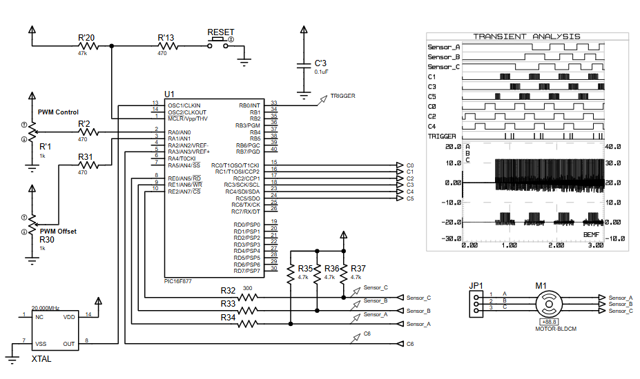
  • How does the project detect rotor position without Hall sensors?
    It measures back electromotive force (BEMF) on the floating motor phase and compares sampled values to half the supply voltage to determine commutation timing.
  • Why is BEMF sampled at 1/4T and 3/4T?
    Sampling at 1/4T and 3/4T helps estimate the zero-crossing point while avoiding noisy edge transitions.
  • Can this project be simulated in Proteus without a motor model?
    No, accurate BEMF behavior requires a BLDC motor model in Proteus VSM for correct simulation.
  • Why is Vsupply divided by two in the detection logic?
    The firmware uses Vsupply/2 as the reference threshold for comparing BEMF to decide acceleration, deceleration, or locked speed.
  • What microcontroller modules are used to implement timing and sampling?
    Timer0, Timer1, ADC, and CCP modules on the PIC16F877 handle timing, commutation triggers, and BEMF/supply sampling.
  • Can this design be ported to other PIC microcontrollers?
    Yes, but timer, ADC, and CCP configurations must be adjusted for the target microcontroller.
  • What happens when PWM is set to maximum?
    The firmware enters full-on mode and disables PWM modulation.
  • Is Hall sensor input supported by this design?
    No, the design is purely sensorless and does not support Hall sensor input.
  • Why is Timer0 used alongside Timer1?
    Timer0 synchronizes PWM timing and speed ramping logic while Timer1 and CCP handle commutation events.
  • Can this control higher-power motors?
    Yes, but appropriate external power drivers and protection circuitry are required for higher-power motors.

About The Author

Ibrar Ayyub

I am an experienced technical writer holding a Master's degree in computer science from BZU Multan, Pakistan University. With a background spanning various industries, particularly in home automation and engineering, I have honed my skills in crafting clear and concise content. Proficient in leveraging infographics and diagrams, I strive to simplify complex concepts for readers. My strength lies in thorough research and presenting information in a structured and logical format.

Follow Us:
LinkedinTwitter