Summary of BOOTLOAD THE PIC18F4550 – FIRMWARE UPDATING
Bootload PIC18F4550 firmware to update the USB interface board by placing the PIC18F4550 into RD/WR (bootload) mode. Use bootloader software (recommend eegeek.net version) to import and write a new HEX file; only RD/WR mode allows writing to the EEPROM. Provided firmware examples control LEDs; tutorial files include MPLAB project, C# application, and bootloader in a BOOTLOAD/DEBUG folder.
Parts used in the PIC18F4550 Bootload Project:
- PIC18F4550 microcontroller
- USB interface board (USB DEMO BOARD)
- LEDs (connected to CTRL1, CTRL2, CTRL3, CTRL4, CTRL7, CTRL8, CTRL5, CTRL6)
- MPLAB project files
- C# bootloader application
- PC with USB port
- HEX firmware file
BOOTLOAD PIC18F4550 – FIRMWARE UPDATING
SETTING THE PIC18F4550 IN RD/WR ( BOOTLOAD ) MODE FOR BOOTLOADING
Loading / updating new code into the USB INTERFACE BOARD can be done with a Bootloader Software. While searching for good bootloader, I found some nice tutorial on eegeek.net and piccoder.co.uk for BOOTLOADING the USB INTERFACE board.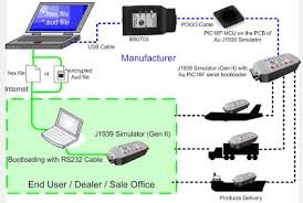
The firmware that is posted in the next tutorial will enable/ allow you to control 6 leds ( connected across CTRL1 , CTRL 2 ,CTRL 3 , CTRL 4 , CTRL 7 ,CTRL 8 – refer schematic below , CTRL 5, and CTRL 6 will flash alternatively)
PIC18F4550 DEMO SCHEMATIC
Piccoder.co.uk and eegeek.net have their own version of Bootloader software. My personal favourite version of BOOTLOADING Software is from eegeek.net , you can download the entire project file of his version of BOOTLOADING software from his website.
The downloaded zip file from eegeek.net will contain entire project file of the USB board, like mplab project, c# application , a BOOTLOADING software in C# and a firmware to control two leds . Search for BOOTLOAD folder inside the zip file and run the bootloading software inside the DEBUG folder (coded in C#).
STEPS OF BOOTLOADING
For loading new code into the USB BOARD it is necessary that the USB BOARD must be set to Bootload mode. There are two modes of a operation, READ mode (you will be able to control this Board only when the board is in READ MODE)and READ/WRITE mode (BOOTLOAD mode).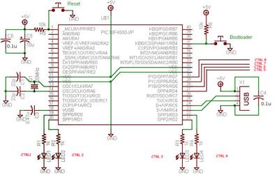
Connect the USB DEMO BOARD to your P.C , and start the BOOTLOADER Software. Import the new hex file that you need to write, into the BOOTLOADING software. [I will provide the new Firmware in my next post]
It is possible to write new code into the EPROM of PIC18F4550 only when it is in RD/WR mode.
For more detail: BOOTLOAD THE PIC18F4550 – FIRMWARE UPDATING
- How do I set the PIC18F4550 for bootloading?
Set the USB demo board to RD/WR (READ/WRITE) mode to enable bootloading. - Can I write new code to the PIC18F4550 in READ mode?
No. Writing new code to the EEPROM is possible only when the board is in RD/WR mode. - What bootloader software is recommended?
The author prefers the bootloading software from eegeek.net and recommends downloading its project files. - What files are included in the eegeek.net download?
The zip contains the MPLAB project, a C# application, a bootloader in C#, and example firmware for two LEDs. - How do I run the bootloading software from the downloaded files?
Locate the BOOTLOAD folder in the zip and run the bootloading software inside the DEBUG folder. - What does the provided firmware control?
Example firmware controls two LEDs; the discussed firmware will control six LEDs with two LEDs flashing alternatively. - How do I import the new code into the bootloader?
Start the bootloader software on your PC, then import the new HEX file into the application. - When should I connect the USB demo board to the PC?
Connect the USB demo board to your PC before starting the bootloader software to perform firmware updates.