Summary of Blue Hunters: Bluetooth RSSI Locator Robots
Two Bluetooth Low Energy robots navigate toward a base station using RSSI measurements and a magnetometer for orientation. Built with PIC32 microcontrollers, 3D-printed chassis, and continuous rotation servos, the project demonstrates short-range distance sensing challenges. The system utilizes OpenSCAD for design, C programming in MPLAB X IDE, and gradient descent algorithms for pathfinding despite signal noise.
Parts used in the Blue Hunters Project:
- PIC32MX250 microcontroller
- HM-10 Bluetooth Low Energy 4.0 module (with TI CC2541 chip)
- MPU-9250 IMU breakout board containing AK8963 3-axis magnetometer
- FS90R continuous rotation micro servos
- 3 AA batteries and battery holder
- Perfboard for circuitry
- Arduino Teensy 3.2 for firmware flashing
- FTDI to USB adapter for serial communication
- 3D printed ABS chassis components (frame, wheels, caster)
Introduction
We built 2 small cars which used Bluetooth Received Signal Strength Indicator (RSSI) measurements to navigate towards a stationary base station. The cars and base station used a Bluetooth Low Energy (BLE) 4.0 module to take the measurements and a PIC32MX250 microcontroller. The cars also used a 3 axis magnetometer as as compass in order to reliably turn, as well as 2 micro 9 g servos to drive. Each unit was powered with 3 AA batteries. Finally, the chassis and wheels of each car were 3D printed.
Video
Design
Chassis
The robots are made from 4 3D printed pieces: 2 wheels, the frame, and the caster in the back. The servos, a 3 AA battery holder, and a perfboard containing all the circuitry are mounted directly to the frame.
The robots where designed in OpenSCAD, and their source code is available in our git repository and below. There are three files, frame.scad, drag.scad, and wheel.scad, for each of the three parts. The main modules are defined in main.scad, and the other files just instantiate them. The following renderings show each part:


The parts were printed in ABS using Maker Select 3D Printer v2 printers. All parts were printed with a layer height of 0.3 mm, as there was no need for a smooth finish or high tolerances. The parts where sliced with Cura.
Pictures
Full system (base station and 2 robots):
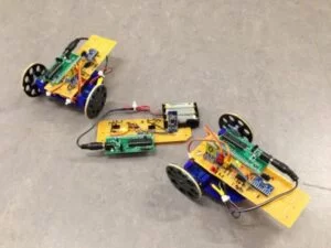
Multiple views of the robots:
Electronics
Bluetooth modules
The HM-10 bluetooth modules we bought off Ebay were fakes: they were not made by Jnhuamao 1, and did not come with genuine Jnhuamao firmware. However, they did have real TI CC2541 chips. We realized they were fakes when they did not behave according to the Jnhuamao data sheet (see the data sheets section). Luckily, the hardware on the fake chips is the same as that of the genuine chips, minus an external crystal, and the genuine firmware checks for the presence of the crystal, and works even without it. 2 As such, we reprogrammed the chips with the genuine firmware according to an Arduino forum post:
- We soldered wires to the programming pins on the breakout boards, and connected those pins to an Arduino Teensy 3.2. We chose a Teensy because it is 3.3 V as opposed to 5, which would damage the 3.3 V CC2541.
The pins were connected as follows:
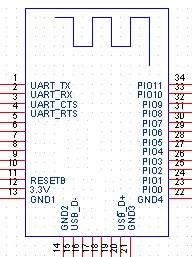
Name CC2541 Pin Arduino Pin DEBUG_CLOCK7 5 DEBUG_DATA8 6 RESET_N11 4 The layout of the HM-10 board is:
- We uploaded the
CCLoader.inosketch to the Arduino. - Finally, we ran (in a Windows virtual machine)
CCLoader.exe. This program takes 3 arguments:CCLoader.exe <COM Port> <Firmware.bin> 0The firmware file came from the same Arduino form post, and can be found here.
There is also an excellent YouTube video, which explains the firmware flashing process.
After flashing genuine firmware onto the chip, the next step was to update the firmware to the latest version. The firmware flashed onto the board was version 540, but Jnhuamao had (at the time we did this project) released version 603. 3 They also provide instructions on how to upgrade the firmware. The basic process is:
- Connect the HM-10 module to a computer using a 3.3 V FTDI to USB adapter. Then, use PUTTY to establish a serial session (9600 baud, 8N1). Send the chip
AT; if it is connected properly, it will respond withOK. - Send the chip
AT+SBLUPto put it in firmware update mode. It will respond withOK+SBLUP. Terminate the PUTTY session. - Run the
HMSoft.exeprogram distributed in the firmware update download. We ran it in a Windows virtual machine because we did not trust it. - Select the proper port and firmware file using the software, and hit “Load Image”. The software should handle the rest!
- To make sure it worked, establish a serial connection again using PUTTY. Send
AT+VERS?to query the chip for version information.
Software
The robots were programmed in C, using the MPLAB X IDE v4.0, with the XC32 v1.4 compiler and the PIC 32 Legacy Peripheral Library (plib). The full source code is available in our git repository and below. The code is divided into 5 main units:
ble.c: contains all the functions for interacting with the BLE device over UART.imu.c: contains all the functions for interacting with the IMU (which contained the magnetometer) over I2C.servo.c: contains all the functions for interacting with the servos using PWM.main.c: the main code.pt_cornell_1_2_2.c: contains the functions which were originally declared in the protothreads header file. However, since they were in the header file, if multiple source files included the header file, there would be linking errors due to duplicate definitions of symbols. Moving the protothreads definitions to a separate file resolved this issue.
BLE
The BLE module used UART, at 9600 baud 8N1. We used UART1 on the PIC for communicating with the BLE module, and used UART2 for communicating with the computer (for debugging). The BLE files define a series of macros and PT_THREAD functions for printing characters and reading lines in a non-blocking fashion using protothreads. All of the PT_THREAD functions can be spawned with PT_SPAWN to run them.
The main.c file contains a thread which does all the communication with the Bluetooth chip using these functions. The commands it sends to the chip are:
AT+RESET: resets the chip to ensure it is in a clean state before receiving other commands.AT+IBEA1: enables the iBeacon functionality of the chip (sets it to 1;AT+IBEA0would disable it by setting it to 0). This allows the chip to be found with an RSSI scan. After setting the value, we query it withAT+IBEA?and send the result over the other serial port to a computer for debugging.AT+ROLE0orAT+ROLE1: sets the role to either peripheral (0) or central (1). The base station is set to peripheral, and the 2 robots are set to central. Peripheral means the device will respond in inquiries from a central device. This allows it to be discovered during an RSSI scan. After setting the value, we query it withAT+ROLE?and send the result over the other serial port to a computer for debugging.AT+IMME0orAT+IMME1: sets the work state of the device to either actively listening for Bluetooth signals (0), or only acting when it receives a serial command (1). Once again, the base station is set to 0: it needs to listen for signals and respond. The robots are set to 1, as the chips need to initiate scan requests when they receive the command over serial. After setting the value, we query it withAT+IMME?and send the result over the other serial port to a computer for debugging.AT+NAME%s: sets the name of the chip (which is visible when scanning) to%s(For example,AT+NAMEPIRATEnames the chipPIRATE). We give all the chips unique names to make debugging easier. After setting the value, we query it withAT+NAME?and send the result over the other serial port to a computer for debugging.AT+SHOW3: configures the device to advertise both its name and RSSI when scanning.AT+ADDR?: queries the device for its hardware address. We recorded the hardware device of each chip, as when doing RSSI scans, the results are reported by hardware address.AT+DISI?: performed only on the robots, causing a discovery scan. The result of the scan is a bunch of lines of the form:OK+DISC:00000000:00000000000000000000000000000000:0000000000:6832A3801EBE:-080The second to last token,
6832A3801EBE, is the hardware address of the discovered device, and the last token,-080, is the measured RSSI. The chip will transmit a line for each device it finds (“line” is a misnomer as it does not separate them with any characters), followed byOK+DISCE.
One interesting thing to note about the chip is that commands do not have to end with newlines or carriage returns. However, if sent, the chip will ignore them.
IMU
The PIC commmunicates with the IMU via I2C. The IMU includes a breakout board for the QFN MPU-9250 module, which itself includes 2 dies. One contains the 3-axis gyroscope and 3-axis accelerometer, which were not used in this project, and the other die is the AK8963 3-axis magnetometer (compass).
It is connected to the rest of the MPU module via an auxillary I2C bus, so it is not connected to the MPU’s main I2C bus by default. While the accelerometer and gyroscope registers can be read after powering up the IMU, the compass also needs pass-through mode to be enabled on the IMU to make it an accessible slave on the I2C bus.
Some useful functions as defined in imu.h are described below:
void imu_init(): Initializes the MPU-9250, including configuring the chip to allow reading the compass.int imu_get_heading()Returns the heading of the robot as a value between -180 and 180. The compasses were not completely calibrated to find magnetic north; it only ensures angles are correct relevant to past headings.void imu_mag_read_data(int * destination)Fetches compass readings; saves register values intodestinationin the form[x, y, z].int angle_diff(int source, int target)Gets the difference between two angles in degrees to account for discontinuity between -180 and 180 degrees.int degree(int deg): Offsets degree values so that they fall within the range -180 to 180 degrees.
Initializing the IMU involves opening the I2C module, and then configuring the IMU.
- We open the
I2C2module;I2C1uses pins already used by the connections to the Bluetooth module. We open it with the baud rate generator valueBRG = (Fpb / 2 / baudrate) - 2 = 4e7 / 2 / 4e5 - 2 = 48, as specified forOpenI2C2()in the peripheral libraries. - Pass through is enabled, interrupts for data ready are enabled, the IMU as an I2C master function is disabled, and the sensor is powered up.
This enables the PIC to talk to the AK8963. The AK8963 has several modes of operation, and the chip must be set to power-down mode before switching to other modes. We read compass values with single measurement mode, as specified below:
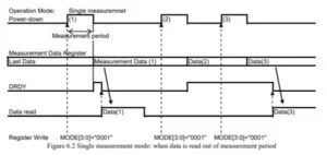
- Set the compass to single measurement mode in 14 bit resolution.
- Read the 6 data registers (X low, X high, Y low, Y high, Z low, Z high)
- Read the Status 2 register to check for magnetic sensor overflow. Without reading this register, the read is not considered complete and further reads will fail.
- Wait; if the IMU is read too frequently, it will not have enough time to take measurements.
Additional helper methods used in I2C were defined in imu.c. These are largely based on the files from the self-balancing robot.
char i2c_read_device(char device, char address)Reads the data from a single register ataddressvoid i2c_write_byte(char device, char address, char data)All configurations used in this project involved writing single bytes of data.void i2c_wait(int cnt)Writes 2 nops; reads require time to return a value, and calling reads consecutively.
In order to calibrate the compass, the robots spun in place when powered on. They recorded the maximum and minimum values for each axes, and used that data to scale and center the magnetometer readings.
Servos
For the drive systems, we used the FS90R servos. These servos are continuous rotation servos with a stall torque of 1.5 kg-cm. Continuous rotation servos operate based on PWM duty cycle; since servos operate at a pulse width of 1 to 2 ms out of 20 ms, we used a timer with a prescaler of 32 and a maximum count of 25600, and set the pwm at numbers ranging from 1280 to 2560 (corresponding to the right pulse width).
A 50% duty cycle means the servos are still. A less than 50% duty cycle means the servo turns clockwise and a greater than 50% duty cycle means the servo turns counter-clockwise. To implement the PWM, we use the output capture on the PIC. We set the duty cycle using the built in timers. We set a max and min duty cycle value which were experimentally derived. The middle point is the average of the two. Tank drive is used to control the system where both wheels are driven forward or point turns where one wheel is turned in one direction and one is turned in the other direction.
Protothreads
While the provided protothreads library was very helpful, it did not work correctly when used in multiple compilation units. The reason for this was that it defined variables and functions in the header file, so if multiple source files included pt_cornell_1_2_2.h, linking would fail with duplicate symbol definitions. Furthermore, if multiple files included config_1_2_2.h, linking would fail with the obscure error:
section `.config_BFC00BF4' will not fit in region `config2'This happened because if multiple compilation units included #pragma config directives (which they did by including a #include "config_1_2_2.h" directive), then the linker would try to assign too many symbols to the configuration region.
The fix to this was twofold:
- We modified protothreads to have both a header and source file, with definitions only in the source file.
- We only included
config_1_2_2.hin the main C file, and moved all macro definitions to the protothreads header.
The updated versions of protothreads can be found in Appendix B.
Gradient descent
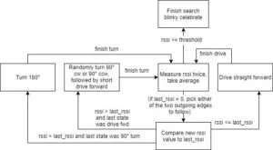
The algorithm for deciding what path to follow is a basic version of gradient descent. The following image represents the decision-making state machine, where the starting state is Measure rssi twice, take average.
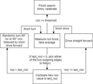
We also implemented and tested the following improved version that allows for correction; a car that has just moved forward and detected a weakened signal does not know whether the beacon to its left or right. If after turning, the signal is still weaker, it has picked the wrong turn. This decision process corrects this (same starting state: Measure rssi twice, take average):
It did not prove much more accurate than randomized gradient descent, largely due to noisy readings from IMU and Bluetooth signal strength. As such, we used the simplified version.
Testing
BLE
Once we flashed the Bluetooth chips with the proper firmware, we used the LightBlue app to test communications. Using the app, we could discover the Bluetooth chips, and send and receive data. By initially using a the iPhone app, which was known to work, we could debug the Bluetooth chips in isolation. Once that worked, we had the chips communicate with each other. Finally, we had the chips take RSSI measurements.
We also experimented with RSSI, as described in results. This data validated the effectiveness of RSSI as an approximate metric for distance measurement, though confirmed that it would be highly variable.
IMU
- Basic I2C: Basic testing was required to ensure I2C communication with the chip was working. This included testing the correctness of the I2C read and write functions (including the order of starts, restarts, and idles in accordance with the I2C protocol and the chip datasheets), as well basic parameters like the address of the MPU-9250 and its registers.
- Compass I2C: This was more complex, and mostly involved testing the usage of the modes of both the MPU-9250 (IMU module) and the AK8963 (the compass itself). Performance testing was also important here, as the compass would not allow rapid reads in quick succession; we inserted nops in the
imu_mag_read_data(int * destination)for this reason. - Compass calibration: We tested incrementally, first using hard-coded maximum and minimum observed values outputted from the IMU, and then with values taken from a self-calibration in which the robot would spin in a circle, and the PIC would record the largest and smallest values it saw on the X- and Y-axes.
Servos
We tested the functionality of servo code by testing individual functionality on both the hardware and software side. We tested the servo code in stages, first implementing control at a fixed speed and then implementing directional motion and lastly turning. This allowed us to verify our parts of the code and the functionality of the servos.
Whole system
- Some subsystem testing was required for the servo with the IMUs, for turning/driving straight with feedback. We debugged by reading in IMU values via UART and observing the robot’s turns.
- We tested extensively with the beacon and two hunters in different environments. Most of our initial testing was in a large, open space with a few metal tables on the periphery. We later tested in the lab in the Digital Lab (Phillips 238), and in the hallway where our demo took place. The confined space of the inside of the lab and hallway, as well as the presence of more reflective bodies (metal doors, tables, people) negatively impacted the performance of our hunters, and it was necessary to recalibrate the hunters to work better in the demo environment.
Results
In most cases, at least 1 of the 2 robots successfully made it to the base station. However, it was not as reliable as we initially hoped. One of the main reasons for this was the noise in RSSI measurements.
We expected that RSSI would vary with distance according to the following relation:
RSSI = A − 10nlog(d)
where A and n are RF propagation parameters in dBm, d is distance in meters, and RSSI is the measured RSSI in dBm. 4 We experimented with RSSI measurements to determine how well they worked by taking 2 Bluetooth modules, and measuring the RSSI while changing the distance between them. One remained stationary on the floor and the other was moved away from it 1 floor tile (each floor tile is a 1 foot square) at a time. At each point, we took 3 RSSI measurements and averaged them. The graph below displays the results:
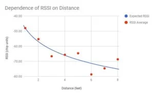
While the chip reported RSSI in units proportional to dBm, and we measured distances in feet, not meters, we could still use the above formula without worrying about unit conversions. The constants A and n, provided we determined them empirically based on the data, would encode the conversions. As such, we fit the data using the above formula with A = −48 and n = 3, resulting in the blue curve above. While the general shape of the curve matches, there is significant noise in the averaged RSSI data. Furthermore, when we tried to reproduce the measurements, we could not do so precisely – it seemed to even depend on where our feet where! See Appendix B for the source data for the table.
Despite how noisy the RSSI measurements where, the robots were still able to perform a reasonably accurate gradient descent. In most cases, at least one of the 2 robots would find the beacon in a matter of minutes.
Conclusions
This assignment was an interesting exploration into short-range distance determination using Bluetooth, a generally unconventional approach. We were warned beforehand about the difficulties in using Bluetooth RSSI, a measurement particularly susceptible to multipath interference, as a distance sensor – both in the papers and reference materials researched before implementation, as well as by course staff in the early stages of our project. We worked with the course staff to simplify and stratify our project into workable milestones. Our final project is a reduced version of our original plan.
Our hunting bots worked reliably when they stayed within roughly 1 m of the beacon. After this, they entered the land of shallow gradients: the signal strength from the beacon (already noisy) would not change very much, and often only due to noise. The hunting bots normally could never recover from this. Our bots also worked better in larger, more open spaces, preferably without metal structures like tables or doors nearby. Both of these are reasonable given the operating range of BLE 4.0.
We reused some of the code from the Self-Balancing Robot as cited in our references section, and explained in IMU. The rest of the design is ours, and is not an infringement on intellectual property. We also used the Bluetooth firmware flashing technique we discovered on the Arduino forums.
We did not reverse-engineer any technology, and did not encounter any issues with trademarks or patents. We did not have to sign non-disclosure to get a sample part. We hope to further polish our findings and report, and will aim to publish them in a print magazine, ideally as a part of ECE 4920.
There are many potential avenues for improvements or further development. In addition to more circumstantial difficulties encountered during the project work period (such as extremely unbalanced servos, where one always ran faster than the other), two areas of potential improvement are as follows:
- Communication between the two robots. While Bluetooth may not offer good distance measurement via RSSI, it can be used for reliable communication between modules. It would be straightforward for one hunting robot to inform the other whether it believes it is approaching the beacon or not. In the simplest case, a hunting robot that is approaching, or already at, the beacon can provide a second point of reference for a currently hunting robot.
- More complete usage of IMU. A lot of development time was spent simply on getting the PIC to compass communication running, and not much time was spent on calibrating the sensor or processing the data. In further stages of this project, we could continue to work towards dead reckoning of the mobile robots. This, paired with inter-swarm communication, would make for a much more sophisticated and likely much more efficient system. (Of course, this does not resolve the shallow gradients problem – but it would allow the approach to the beacon to be much faster.)
IEEE Code of Ethics
Our project, as well as the design and creation project thereof, adheres to the IEEE Code of Ethics. The project itself is relatively small and physically self-contained; it did not have any immediate impact on the environment or safety and health of potential users, we the creators, or any others. We chose the project’s topic out of interest and for a challenge, without any conflict of interest. Our report is honest and realistic; none of our data is fabricated, and our conclusions reflect our hard findings. We did not accept any form of bribery.
The project investigated the use of an emerging and popular technology (BLE) in a new application (distance sensing). We consistently received and built upon advice from our TAs and professor Bruce Land, and cite the work we used in the basis of our project.
Additionally, neither we nor our project presented any act of discrimination, and our project does not injure others in any way. We assisted our colleagues (both fellow group members and other classmates) when the occasion arose, such as by offering help debugging or lending a spare module before a demo.
Overall, our project complies with the IEEE Policies, 7.8 Code of Ethics.
Source: Blue Hunters: Bluetooth RSSI Locator Robots
- How were the HM-10 Bluetooth modules programmed?
They were soldered to an Arduino Teensy 3.2 via specific pins to upload genuine firmware using CCLoader.exe. - What algorithm determines the robot's path?
The project uses a basic version of gradient descent to decide which direction to move based on RSSI changes. - Which microcontroller is used for the robots?
The robots utilize the PIC32MX250 microcontroller. - How are the servos controlled?
Continuous rotation FS90R servos are driven by PWM duty cycles generated by output capture timers on the PIC. - What role does the magnetometer play?
The 3-axis magnetometer acts as a compass to ensure the robots can turn reliably. - How was the IMU calibrated?
The robots spun in place when powered on to record maximum and minimum values for scaling and centering the magnetometer readings. - Why did the team use OpenSCAD?
OpenSCAD was used to design the 3D printed chassis parts including the frame, wheels, and caster. - What environment affected the robot performance most?
Confined spaces with reflective metal structures like tables and doors negatively impacted the RSSI performance.