Summary of Digital Voltmeter (0-50v) using PIC Microcontroller
This article explains building a digital voltmeter using a PIC16F877 microcontroller. It utilizes the chip's internal 10-bit ADC to measure voltage, converting the data for display on an LM106L LCD connected to Port D. A voltage divider circuit with specific resistors scales input voltages up to 50V down to a safe 5V range for the microcontroller. The system calculates equivalent integer values based on a 5V reference to ensure accurate readings.
Parts used in the Digital Voltmeter:
- PIC16F877
- LCD (lm106l)
- Resistors (100k & 11.11k)
If we know how inbuilt ADC work then we can easily build Digital Voltmeter using PIC Microcontroller. In my previous post, we can see how easily we build “Digital thermometer with auto saving log file in excel by Pic microcontroller”. Using the same principle here we build Digital Voltmeter using PIC Microcontroller.
Requirement:
To make digital voltmeter we uses some material here I give you the list of that.
1) PIC16F877
2) LCD (lm106l)
3) Resistors (100k & 11.11k).
Project Details:
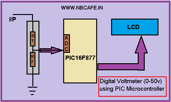
In this project we use internal ADC of PIC16f877 microcontroller for getting input voltage which we have to measure. After getting the input it processed in microcontroller and the equivalent voltage is display in the LCD which is attached with port D. In bellow see the block diagram of our project Digital Voltmeter using PIC Microcontroller.
Working Principal:
We know that PIC16f877 has 10 bit ADC. So input in form 10 bit and we need 8 bit data to farther process. So getting equivalent integer value we have to convert the 10 bit ADC value in equivalent integer number. Now question is how we convert it? For converting it we have to take a reference voltage let we take reference voltage 5 volt. Now the formula of conversion is
Value =value * (reference millivolt / 210-1)
=value * 5000/1024-1
= value * 4.89
Now here we can use maximum reference voltage 5 Volt beyond that voltage PIC cannot tolerate. Now if we give max 5v as reference then how can we measure 50v? We cannot give 50v at input pin of in build ADC for measure 50 v DC. So we have to reduce the voltage with proportionate with reference voltage 5v. For that reason here we introduce Voltage divider circuit with taking R1 = 100k and R2 = 11.11k. Now for selecting R1 and R2 we use voltage divider formula I,e
Vout = (R2/R1+R2) * Vin .
So using above formula let see what happen if we want to measure 50v
Vout = (11.11/100+11.11)*50
= 5v
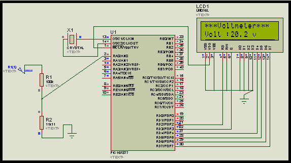
So we can easily measure maximum 50 v DC. See the circuit diagram for proteus simulation.
For more detail: Digital Voltmeter (0-50v) using PIC Microcontroller
- What components are required to build this digital voltmeter?
The project requires a PIC16F877, an LM106L LCD, and resistors of 100k and 11.11k. - How does the PIC16F877 handle the input voltage measurement?
It uses its internal 10-bit ADC to capture the input, processes it, and displays the equivalent voltage on the LCD. - Why is a voltage divider circuit necessary in this design?
A voltage divider is needed to reduce high input voltages, such as 50V, down to a maximum of 5V which the PIC cannot tolerate beyond. - What formula is used to convert the 10-bit ADC value to an integer?
The conversion formula is Value = value * (reference millivolt / 1024-1), which simplifies to multiplying by 4.89 for a 5V reference. - How do the selected resistor values allow measuring up to 50V?
Using R1=100k and R2=11.11k in the voltage divider formula results in exactly 5V output when 50V is applied at the input. - Can the built-in ADC accept more than 5 volts directly?
No, the PIC cannot tolerate a voltage beyond 5V at the input pin of the built-in ADC. - Where is the LCD connected in the circuit?
The LCD is attached with Port D of the microcontroller.