


Summary of Automatic Charger Sharing for Motorcycle Battery Charger using PIC16F628A
This project is a four-way automatic battery charger sharing controller for motorcycle batteries. It cycles a single smart charger among four bike connections, connecting each for about 8 hours (32-hour full cycle), detecting which outputs have bikes connected, and skipping unused channels. LEDs show heartbeat and per-output status (off, blinking, steady). Switching includes a 30-second disconnect interval so the charger resets. It is tested with an OptiMate 4 in standard mode; users must ensure batteries are in good condition and avoid CAN-bus chargers or heavily discharged batteries.Parts used in the Automatic Charger Sharing for Motorcycle Battery Charger:
- PIC16F628A microcontroller
- OptiMate 4 smart charger (tested charger)
- Control board with five LEDs (one green heartbeat LED, four orange output LEDs)
- Power switching components to connect/disconnect charger to four outputs (relays or MOSFETs as used on board)
- Battery connection terminals or harness for four motorcycle outputs
- Resistors and current-limiting components for LEDs
- Passive components for microcontroller operation (capacitors, crystal or oscillator components)
- PCB or prototyping board and enclosure
- Wiring and connectors for charger and bike battery connections
Description
This project came about because I have three motorbikes and being a bit of a fair weather biker they don't get used much over the winter months. I have an OptiMate™ 4 charger
that I connect to the bikes but this needs me to manually swap it from one bike to the next and between forgetting to do it and not remembering which bike it was last connected to it's all a bit unreliable.
So this project is an four-way automatic battery charger sharing controller. The circuit is powered from the battery(s) of the connected motorbikes. Current consumption is about 40-50mA and since it draws its power from the battery under charge it doesn't discharge the batteries on the other bikes.
The circuit continually monitors which of the four connections are in use so it only connects the charger to outputs that are currently connected to a bike. If a bike is disconnected part way through charging the circuit immediately switches to the next connected output.
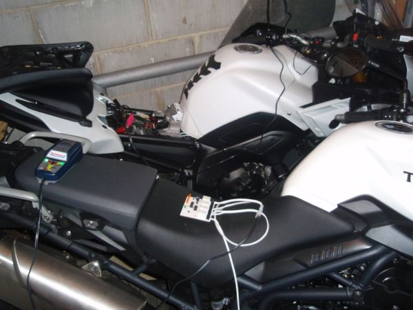
Status LEDs show which output is currently connected to the charger, which outputs are connected to a bike but not currently charging and a heartbeat LED to indicate the microcontroller is operating normally.
Please read the Caveat before using this project
Operation
This controller project has only been tested using an OptiMate™ 4 'smart' charger in standard mode (not CAN-bus). It should work with other chargers, however, it hasn't been tested and I am unable to advise on this.
The controller connects each output to the charger for approximately 8 hours. The controller cycles through all four outputs over a 32 hour period (4 x 8hrs)
When switching from one bike to the next, all outputs are disconnected for about 30 seconds to allow the charger to see the disconnection and reset itself.
If no bike is detected on an output the controller simply skips that output and goes to the next one in the cycle. If only one bike is connected, after eight hours it is disconnected for 30 seconds and then reconnects for another 8 hours.
There are five LEDs on the control board.
The green heartbeat LED blinks continually, once per second to show the controller is operating.
Four orange LEDs indicate the status of each output/bike connection.
- If the LED is off, no bike is detected and the channel is skipped.
- If the LED is steady on, the charger is connected to the output.
- If the LED blinks briefly every 2.5 seconds, a bike connection is detected on the output but the charger isn't currently connected to it. This just gives visual confirmation that the controller knows the bike is connected.
- If a battery is disconnected while charging, the controller waits 30 seconds before assuming the battery has disconnected. The output LED stays on during this time.
Any of the outputs can be connected at any time. They don't need to be connected sequentially. The controller will skip outputs that aren't connected. However, you should note that when you connect another bike it may be up to 24 hours (3 x 8 hours) before its output gets connected to the charger.
Important Notes:
- The charger is designed to work with 12 volt electrics and charging currents not exceeding 3 amps.
- Before using this controller, all the batteries should be in good condition and charge state, if necessary charge then directly from the charger.
- The charge share controller will help to maintain healthy batteries in a good state of charge. If you have a battery that is heavily discharged or sulphated don't connect it to this controller.
- Don't use on bikes equipped with a CAN-bus or charger set to CAN-bus mode as switching from one battery to another can confuse the 'smart' charger.
- When the charging is done through the controller the status indicators on the charger only show the condition of the battery currently being charged. Therefore periodically you should connect the charger directly to each bike to ensure the batteries are all charging correctly.
- When the control board output(s) are connected to one or more motorbikes, the controller starts to operate. This occurs even if the battery charger isn't connected so you should make sure the controller isn't connected to the bike(s) if the charger is turned off or disconnected for any length of time. Although the controller only uses about 50mA it will eventually run the bikes battery down if the charger isn't present for several days.
For more detail: Automatic Charger Sharing for Motorcycle Battery Charger using PIC16F628A
- How long does each output get connected to the charger?
Each output is connected for approximately 8 hours. - What happens when switching from one bike to the next?
All outputs are disconnected for about 30 seconds to allow the charger to see the disconnection and reset itself. - Will the controller work if a bike is disconnected during charging?
If a battery is disconnected while charging, the controller waits 30 seconds before assuming the battery has disconnected and the output LED stays on during this time. - How does the controller indicate which outputs have bikes connected?
Four orange LEDs show output status: off means no bike detected, blinking every 2.5 seconds means bike detected but not charging, and steady on means charger is connected to that output. - Does the controller draw power from the batteries?
Yes, the circuit is powered from the connected batteries and consumes about 40-50 mA. - Can I use the controller with any charger?
The project has only been tested with an OptiMate 4 in standard mode; it should work with other chargers but this has not been tested or advised on. - Can I use this on bikes with CAN-bus systems?
Do not use on bikes equipped with a CAN-bus or with the charger set to CAN-bus mode because switching can confuse the smart charger. - What should I do before using this controller?
Ensure all batteries are in good condition and state of charge; charge any heavily discharged or sulphated batteries directly from the charger first. - Do the charger indicators show the state of all batteries when using the controller?
No, the charger indicators only show the condition of the battery currently being charged, so periodically connect the charger directly to each bike to verify charging.
Related projects
DHT11 Low Cost Humidity Sensor using PIC16F628A with Proteus Simulation
IntroductionThis microcontroller project demonstrates how to interface a low-cost DHT11 temperature and humidity sensor with a PIC16F628A using a Proteus simulation environment.The...
LCD & Display Projects · PIC16F628AFrequency Counter by PIC16F628
In this project we are building a basic and low cost frequency counter circuit . It can measure from 16Hz to 100Hz...
Games, Toys & Calculators · PIC16F628ATIC TAC TOE game using PIC16F628
This project is not to introduce Tic Tac Toe. Everyone knows this game. It's to introduce two features. Bi-coloured LEDs, microcontrollers and...
Motors & RoboticsReal-Time CAN-Based Vehicle Monitoring System with PIC MCU
INTRODUCTION The Controller Area Network (CAN) is a robust vehicle communication bus standard that was primarily developed for automobile applications but has...
Motors & RoboticsEasy Way to Learn Robotics Using Microcontrollers: A Beginner’s Guide
The title, "Easy Way to Learn Robotics Using Microcontrollers," promises an accessible entry point for those curious about the exciting world of...
Motors & Robotics · PIC16F877AEfficient Sun-Following Robot: A Solar Tracker with Microcontroller Control
Abstract The impending global challenge of dwindling non-renewable fuel resources underscores the urgency of transitioning towards renewable energy alternatives like solar power....

Ibrar Ayyub
I am an experienced technical writer holding a Master's degree in computer science from BZU Multan, Pakistan University. With a background spanning various industries, particularly in home automation and engineering, I have honed my skills in crafting clear and concise content. Proficient in leveraging infographics and diagrams, I strive to simplify complex concepts for readers. My strength lies in thorough...