Summary of Audio Equalizer / Tone Control Circuit with Bass, Treble and MID Frequency Control using Op-Amp
This article details the design of a three-band active tone control circuit using an Op-Amp (TL072) to manage bass, mid, and treble frequencies. Powered by 12V, the circuit utilizes RC filters and potentiometers to adjust cutoff frequencies via specific formulas. The project includes a complete schematic explanation covering buffering, filtering stages, and biasing for single-rail operation, alongside instructions for designing and assembling the PCB.
Parts used in the Tone Control Circuit:
- 100k- potentiometer - 2 pcs
- 470k- potentiometer - 1 pcs
- TL072 operational amplifier
- 12V power supply
- .1uF 35V Capacitor
- 1.2nF 63V Capacitor
- 100uF, 35V Capacitor
- 10uF, 35V Capacitor
- 2.2uF, 63V Capacitor
- 22k resistor
- 22nF 63V capacitor
- 270R resistor
- 33pF capacitor
- 4.7nF 63V capacitor - 2 pcs
- 47nF Capacitor
- 1.8k resistor - 2 pcs
- 10uF, 25V Capacitor - 2 pcs
- 3.3k resistor - 2pcs
- 47k resistor - 2pcs
- 10k resistor - 5pcs
- PCB
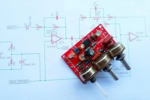
Tone control or Active equalizer circuit especially bass, treble, and MID control based Equalizer is an important circuit in audio amplifier design. Generally, three-stage active Equalizer filters require three control bass, treble, and MID. The bass control allows the low frequency to pass but blocks high frequency and the treble control allows the high frequency to pass but blocks low frequency, whereas the MID control balances between high and low frequency. In this project, we will design an active Tone control circuit powered by an op-amp with a PCB design. It will work with a 12V power supply and will have bass, treble, and mid-frequency control so that the output audio can be adjusted as required. You can also check out the other bass treble circuits which we have build earlier.
- Stereo Audio Pre-Amplifier with Bass and Treble control using Transistors
- Simple Audio Tone Control Circuit with Bass and Treble Control
- High Power Bass and Treble Control Circuit using LA4440
For this project we used PCBWay‘s PCB manufacturing services to make our circuit boards. In the following sections of the article we have covered the complete procedure to design, order and assemble the PCB boards for this audio equalizer circuit.
Components Required
The components required to build this Tone control circuit using Op-Amp is given below.
- 100k- potentiometer – 2 pcs
- 470k- potentiometer – 1 pcs
- TL072 operational amplifier
- 12V power supply
- .1uF 35V Capacitor
- 1.2nF 63V Capacitor
- 100uF, 35V
- 10uF, 35V
- 2.2uF, 63V
- 22k resistor
- 22nF 63V capacitor
- 270R resistor
- 33pF capacitor
- 4.7nF 63V capacitor – 2 pcs
- 47nF
- 1.8k – 2 pcs
- 10uF, 25V – 2 pcs
- 3.3k – 2pcs
- 47k – 2pcs
- 10k – 5pcs
- PCB
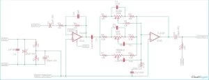
Audio Equalizer Circuit Diagram
The complete bass treble circuit diagram is shown in the image below. The major component in this circuit is the Op-Amp. The Op-Amp TL072 is a popular operational amplifier that has two individual operational amplifiers in a single monolithic package.
Op-Amp Buffer Circuit:
The IC1A is configured as an inverting buffer amplifier. This buffer amplifier provides a buffered output of the input signal to be filtered or equalized by the three-band filters. The capacitor C4 is a blocking capacitor that blocks the DC signal and only allows the AC signal to pass.
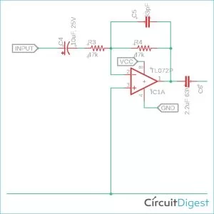
The resistors R3 and R4 need to be accurate and matched. It is recommended not to alter these two values at this stage. The output 2.2uF, C6 capacitor will pass the signal from the buffered output.
Mid Frequency, Bass and Treble Control Circuit:
In the next stage, IC1B is the actual active filter that has three pass filters connected across the negative feedback loop. Here is the actual tone filtration is happening-
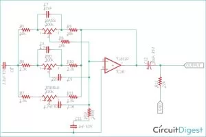
The negative input is received from the 2.2uF capacitor. The op-amp IC1B is again configured as an inverting amplifier and it is taking an inverting input from the IC1A and at the output, it is again inverted.
The three-band filters are both RC filters. Since the capacitor values cannot be changed, the resistor value is changed over here by using a variable potentiometer. Here, the resistor R12 and capacitor C11 are used as the gain setting. Changing the R12 value will also change the gain.
In the first filter that is the bass filter (low pass). The first network circuit is R8, Bass potentiometer and R9 is the total resistance of the filter and the capacitor is C7. To determine the cutoff frequency, one can use the below formula-
fc = 1 / 2piCR
The fc is the cut off frequency and C is the capacitor value, the R is the total resistance of the network. Therefore, changing in different pot values or changing the C7 capacitor will change the frequency response of the Bass filter (Low Pass filter).
Calculating Cutoff Frequency for Bass and Treble Circuit:
For example, in the above circuit, the potentiometer value is 100k. Therefore, The total resistance, 100k (Bass Pot) + 10k (R8) + 10k (R9) = 120k. Thus as per the formula, the bass control could process the frequency up to 28 Hz.
The same thing happens for the MID filter. But instead of a low pass or high pass filters, it uses a bandpass filter construction.
The cutoff frequency can be obtained using the same formula fc = 1 / 2piCR. The highest band can be calculated using the resistor R6 and capacitor C8 (as per the schematic value, it is 10.2 kHz) and the lowest band can be calculated using the – MID potentiometer value + R10 as the total resistance and capacitor C9 (as per the schematic value, it is 70 Hz).
In the last filter band, it is a treble tone control with a high pass filter. The formula doesn’t change, it is the same fc = 1 / 2piCR. The total resistor is the Treble resistor, and the R11 and the capacitor are the C10. When the treble is completely low, that means the potentiometer is fully 470k using the schematic value, the cutoff frequency of the filter is – 71 Hz. But during the full treble mode, when the potentiometer is completely turned on, the resistance of the potentiometer becomes insignificant and only the resistor R11 takes into effect. In this situation, the cutoff frequency became -18 kHz. The output is obtained from the C12.
Biasing/Offset Circuit:
Since this is a single rail supply voltage where the negative rail is not used, the input signal needs to be offset. This is due to the inability of the op-amp to amplify negative peaks of the input signal in a single rail power supply mode.
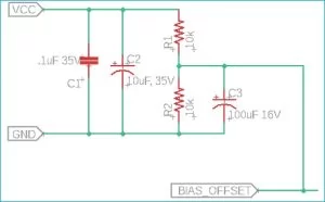
To make the offset, a voltage divider is placed across the positive feedback of the op-amp. The voltage divider will offset the signal half of the supply voltage. Since it is using 12V supply, the input signal is offset by 6V DC. The C1 and C2 are the filter capacitors and the R1 and R2 are used to make the voltage divider along with an additional filter capacitor C3.
Active Audio Filter PCB Design
The PCB for our Active Audio Filter circuit is designed for a double sideboard. I have used Eagle to design my PCB but you can use any Design software of your choice. The 2D image of my board design is shown below.
Source: Audio Equalizer / Tone Control Circuit with Bass, Treble and MID Frequency Control using Op-Amp
- What components are required to build this Tone control circuit?
The project requires two 100k potentiometers, one 470k potentiometer, a TL072 op-amp, a 12V power supply, various capacitors ranging from 33pF to 100uF, multiple resistors including 10k, 22k, and 47k, and a PCB. - How does the bass control function in this circuit?
The bass control acts as a low-pass filter where changing the potentiometer value or capacitor C7 alters the cutoff frequency, allowing low frequencies to pass while blocking high frequencies. - Does the circuit use a single rail power supply?
Yes, the circuit operates on a single 12V rail supply, which requires a voltage divider to offset the input signal by 6V DC to handle negative peaks. - Can I change the capacitor values to alter the frequency response?
While the text notes that resistor values are changed via potentiometers to adjust gain and frequency, it implies capacitor values like C7 define the baseline response, though it explicitly states resistor R12 changes gain. - What is the role of the TL072 IC in this design?
The TL072 contains two individual operational amplifiers; IC1A acts as an inverting buffer amplifier, while IC1B serves as the active filter for the three-band tone controls. - How is the cutoff frequency calculated for the Bass filter?
The cutoff frequency is calculated using the formula fc = 1 / 2piCR, where R is the total resistance of the network including the potentiometer and fixed resistors. - What type of filter construction is used for the MID frequency?
The MID filter uses a bandpass filter construction rather than a simple low-pass or high-pass filter. - How does the Treble control affect the output frequency range?
When fully low, the treble cutoff is 71 Hz, but when fully turned on, the potentiometer resistance becomes insignificant, raising the cutoff frequency to 18 kHz. - Why is a voltage divider placed across the positive feedback of the op-amp?
The voltage divider offsets the input signal by half the supply voltage (6V) because the op-amp cannot amplify negative peaks with a single rail power supply. - What software was used to design the PCB for this project?
The author used Eagle to design the double-sided PCB, though any design software can be used.