he main purpose of the circuit is to control the gate of the house. This DC motor and provided with two limit switches is provided by mechanical parts. The two buttons open and close the circuit inside is available…. Electronics Projects, AT89C51 L293D DC Motor with Door Control Circuit “8051 example, avr project, keil example, microcontroller projects,
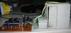
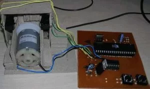
The main purpose of the circuit is to control the gate of the house. This DC motor and provided with two limit switches is provided by mechanical parts. The two buttons open and close the circuit inside is available. Sent to the ends of the drive motor integrated into 1 and 0 knowledge engine is turning left or right.
AT89C51RD2 switches are connected in series to the output port. As soon as the door closed one of the key information by sending port is disconnected. When the other button is pressed, this time the information is sent to one of the other ports and the engine returns to the other side and this time it is connected to the switch port opens.
L293D DC MOTOR DOOR CONTROL
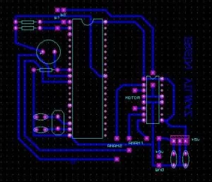
L293D DC MOTOR DOOR CONTROL SCHEMATIC PCB
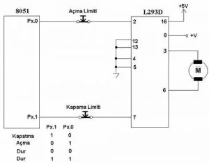
Output Ports Connection Diagram with Motor Drive
AT89C51 L293D DC Motor with Door Control proteus isis schematic pcb keil source code
FILE DOWNLOAD LINK LIST (in TXT format): LINKS-1385.zip