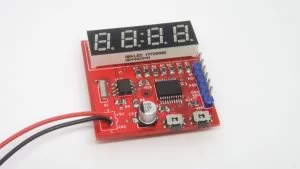
This is a minimal and small clock based on PIC16F628A microcontroller and DS1307 RTC IC. It is able to only show the time on a small 7-segment display with a total of 4 segments. The display we used is a 0.28″ SR440281N RED common cathode display bought from LCSC.com, but you can use other displays as well such as the 0.56″ Kingbright CC56-21SRWA. This project is heavily inspired by the “Simple Digital Clock with PIC16F628A and DS1307” in the case of schematic and we also used the same .hex as”Christo”.
SCHEMATIC
The schematic is straight forward. The heart is the PIC16F628A microcontroller running on the internal 4MHz oscillator, so no external crystal is needed. This saves us 2 additional IOs. The RESET Pin (MCLR) is also used as input for one of the buttons. All display segments are connected to PORTB and COMs are connected to PORTA. The RTC chip is also connected to PORTA using the I2C bus.
The refresh rate of the digits is about 53Hz and there is no visible flickering. The display segments are time-multiplexed and this makes them appear dimmer than the specifications. To compensate we are going to use some low resistors on the anodes. “Christo” tested it with different values for current limiting resistors R1-R7 and below 220Ω the microcontroller starts to misbehave (some of the digits start to flicker) above 220 Ohm everything seems OK. On the display we used the two middle dots are not connected to any pin on the package, so for the seconds’ indicators, we used the “comma” dots. These pins are connected to the SQW pin of the DS1307, which provides a square wave output with 1 sec period. The SQW pin is open drain, so we need to add a pull-up resistor. Τhe value of this resistor is chosen at 470Ω, after some trial and error testing. On the input side of the MCU, there are two buttons for adjusting the MINUTES and HOURS of the clock as indicated on the schematic. Onboard there is also an ICSP Programming connector, to help with the firmware upload. Finally, there is one unused pin left (RB7), which can be used for additional functionality, like adding a buzzer or an additional LED.
The DS1307 RTC needs an external crystal to keep the internal clock running and a backup battery to keep it running while the main power is OFF. So, the next time you power ON the clock the time would be current. To keep the overall board dimensions small we used a CR1220 battery holder with the appropriate 3V battery. Power consumption is about 35-40mA @ 5V input.
CODE
According to the author, the code is written and compiled with MikroC Pro and uses the build-in software I2C library for communicating with RTC chip. If you want to use MPLAB IDE for compiling the code you should write your own I2C library from scratch. For programming the board we used PICkit 3 programmer and software. In this case, in the “Tools” menu check the option “Use VPP First Program Entry“.
Read more: 7-SEGMENT MINI CLOCK USING PIC16F628A AND DS1307 RTC

