
Summary of ANTENNA CONTROL X-Y WITH PIC16F876 PICBASIC
This article describes a second-generation XY antenna control system using the PIC16F876A microcontroller, designed for model aircraft weighing up to 3.2 kg. Developed with Microcode Studio Plus and PicBasic, the circuit features four directional buttons, voltage regulation from 7.4V to 18V inputs, and connections for two servo motors. The design improves upon a previous version by eliminating USB power dependency in favor of dedicated regulated power sources.
Parts used in the XY Antenna Control System:
- PIC16F876A Microchip
- 4 Buttons (Position X and Y)
- LM7805 Voltage Regulator
- Servo/Motor connectors (2 direct connections)
- Blue Connector (7.4-18V input)
- Black Connector (7.4-18V input)
- ICSP Connector for Programming
- TX-RX Data transmission connector
XY antenna, motor control circuit PIC16F876 with 4 buttons on the control board can be made Microcode Studio Plus software and prepared with Pic basic resource. Press code and PCB files there. Control System Antennas (X and Y) This… Electronics Projects, Antenna Control X-Y with PIC16F876 picbasic “microchip projects, microcontroller projects, pic16f876 projects, picbasic pro examples,
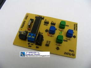
XY antenna, motor control circuit PIC16F876 with 4 buttons on the control board can be made Microcode Studio Plus software and prepared with Pic basic resource. Press code and PCB files there.
CONTROL SYSTEM ANTENNAS (X AND Y)
This is the second version of the plate created since the first try performed by taking the food from any USB port computer and avoid having a source of food, but given the consumption of 2 engines (in my case, to serve as a model aircraft 3.2 kg. force even) I desistimado the first version and in this second I have things improved version of the first.
Data from the plate:
PIC: 16F876A (Microchip)
Speed: 4 Mhz
Programming: frontend Microcode Studio Plus 2.1.0.6 + Picbasic 2.46
4 Buttons Position X and Y
1 reset button Software
4 out of 5 Volt Regulated
1 input voltage (between 7.4 and 18 volts) – Blue connector
1 input voltage (between 7.4 and 18 volts) – Black Connector
1 Regulator LM7805 (regulating the voltage to 5 volts)
1 connector ICSP for Programming INBOARD (without having to make the Micro) + Debugging
2 direct connections to 2 Servos / motors with their food regulated 5V
2 Connecting for data transmission to the outside or with other CIP (TX – RX)
Antenna Control X-Y with PIC16F876 picbasic source code pcb
FILE DOWNLOAD LINK LIST (in TXT format): LINKS-1244.zip
Source: ANTENNA CONTROL X-Y WITH PIC16F876 PICBASIC
- What software is used to prepare the code?
The code is prepared using Microcode Studio Plus software and Picbasic resources. - Can this system be powered via a computer USB port?
No, the second version avoids taking power from any USB port computer to prevent power source issues. - Does the system support multiple voltage inputs?
Yes, it has two input voltage connectors accepting between 7.4 and 18 volts. - How many motors can this control board drive?
The system includes direct connections to 2 Servos or motors. - What is the clock speed of the microcontroller?
The PIC16F876A operates at a speed of 4 Mhz. - How are the directional controls implemented?
There are 4 buttons positioned for X and Y axis control. - Is an external programmer required for updates?
No, an ICSP connector allows programming without removing the chip from the board. - Can this system communicate with other devices?
Yes, there is a connecting port for data transmission to the outside or with other CIP units.
