
Summary of Analog Input Using PIC Microcontroller (assembly Language)
This tutorial explains how to read an analog input with a PIC16F887 using assembly language, covering hardware wiring with a PICkit (power, VDD/VSS, MCLR pull-up, PGD/PGC connections), MPLAB X project setup using mpasm, adding the assembly source, and running the program. It mentions a demo board vs breadboard differences and links to a C-version reference and SFR explanations.
Parts used in the Analog Input Using PIC Microcontroller (assembly Language):
- PIC16F887 microcontroller (40-pin)
- PICkit programmer
- Breadboard or development board
- Power supply or PICkit target power (set to 3.375V)
- 4.7k–10k resistor (MCLR pull-up)
- Wires/jumpers for VDD, VSS, PGD, PGC connections
- Optional: PGM pin left unconnected
- PC with MPLAB X IDE installed
So this tutorial should show you how to get an analog input using a PIC microcontroller (I’m using a PIC16f887) in assembly language. You may have a demo board (which makes programming way easier) just a chip. I’m using just a plain 40 pin chip on a breadboard.
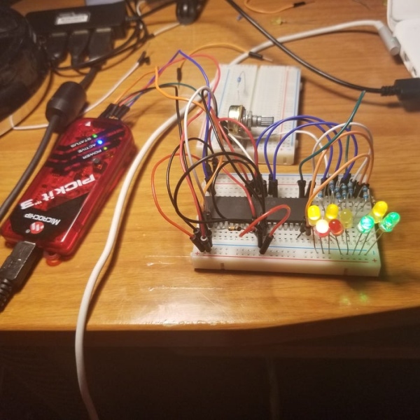
Step 1: Hardware Setup
-You will need a PICkit programmer
- I am using a PIC chip on a breadboard. If you are using a dev board then you can probably disregard some of this since it should plug right in. I have the following setup:
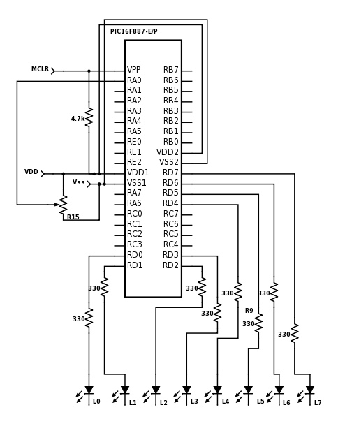
- Hookup VDD and VSS between PICkit and chip (there may be multiple VDD,VSS pins…connect them all)
- PICkit MPCLEAR to MPCLEAR PIN of chip
- MPLCLEAR PIN of chip has 4.7k-10k resistor (this is important) connected to VDD (if you are just using a chip only)
- PGD pin of PICkit to PGD on board
- PGC pin of PICkit to PGC on board
- PGM pin on PICkit is left unconnected
Follow the attached diagram to hookup the the entire circuit.
Step 2: Software Setup
You need MPLAB X IDE installed if you don’t have it already.
- Open MPLAB
- File->New Project
- Microchip Embedded->Standalone Project
- Select Your Chip from the list (mine is a 16F887)
- Select PICkit under the hardware tools
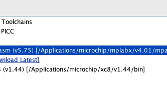
- Select mpasm
- Set your project name and save locations
Now that you created the project, let’s configure some of the properties
- In the project tree that just got created on the left, right click the project and select properties
- Select PICKit on the left hand side
- Select power from the dropdown list
- Check the power the target device and set the voltage level 3.375
- In the project tree, right click the source folder and add a general asm file
- Open the .asm file and past the code from the attached .txt file
Attachments
Step 3: Wrap-up
Assuming there was no copy and paste formatting errors and you changed the appropriate code if you use a different microcontroller, you should be ready to hit the green play button.Check this out if you want to see how to essentially do this in C instead of assembly while still using MPLAB. There is also a good explanation of some of the special function registers (SFRs) used in analog to digital conversion in it as well.
Source: Analog Input Using PIC Microcontroller (assembly Language)
- What microcontroller is used in this tutorial?
The tutorial uses a PIC16F887 microcontroller. - Can I use a breadboard for this project?
Yes, the author uses a plain 40-pin PIC on a breadboard and provides wiring details for that setup. - How should MCLR be wired for a chip-only setup?
MCLR should have a 4.7k–10k resistor connected to VDD as a pull-up. - Do I need to connect the PGM pin on the PICkit?
No, the PGM pin on the PICkit is left unconnected in this tutorial. - What software is required to assemble and program the PIC?
MPLAB X IDE with mpasm is used to create the project and assemble the code. - How do I power the target device when using PICkit?
Select PICKit in project properties, choose power, check power the target device, and set the voltage to 3.375V. - Where do I add the assembly code in MPLAB X?
Right click the source folder in the project tree, add a general .asm file, and paste the assembly code into it. - What PICkit connections are required for programming?
Connect VDD and VSS between PICkit and chip (all VDD/VSS pins), PGD to PGD, PGC to PGC, and MPCLEAR to the chip MCLR. - Is there a reference for doing this in C?
The tutorial links to a C version that also explains relevant special function registers for ADC.
