
Summary of An “Antique Radio” Christmas Present
This article details the creation of "Radio Betty," a custom MP3 player disguised as an antique radio for the author's mother-in-law. The project utilizes a MicroMite microcontroller to manage an LCD display, encoders, a real-time clock, an IR receiver, and an MP3 module. The build involves designing and ordering a PCB from China, soldering components, fabricating a custom front panel with laser-cut acrylic and printed graphics, and constructing a wooden cabinet using poplar and plywood.
Parts used in the Radio Betty:
- MicroMite controller
- 2004 LCD display
- Two KY-040 encoders
- Serial MP3 module
- DS3231 real time clock
- Infrared receiver (TSOP4838)
- 1/8" black acrylic
- .040 clear acrylic
- 4-40 flat head screws
- Stacked nuts (spacers)
- 3/4" poplar wood
- Plywood
I happen to be part of the 5% that have the elusive awesome mother-in-law. For Christmas I wanted to make her an “antique radio” that is super simple to operate and that could play some “old time radio” type programming that she listened to when she was a young’n. However, this is neither an antique or a radio, its an MP3 player. I named it “Radio Betty” after her.
Step 1: The MicroMite controller
I had been playing with a pic microcontroller that has a built in basic interpreter, that cost only $4.00. The MicroMite was introduced by Geoff Graham of the MaxiMite computer fame, and it has turned out to be a great little controller for many of my projects. It is super simple, yet powerful for such an affordable chip. The built in functions of this powerful little beast allowed me to implement a 2004 lcd display, two KY-040 encoders, a serial MP3 module, a DS3231 real time clock and an Infrared receiver to make a nice “antique radio” without pulling out what little is left of my hair.
His website describing the MicroMite is http://geoffg.net/micromite.html and there is a great user forum at www.thebackshed.com
A video review of the chip can be found here.
Take a look at this for your next microcontrolled project.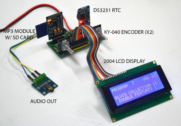
Step 2: The Circuit
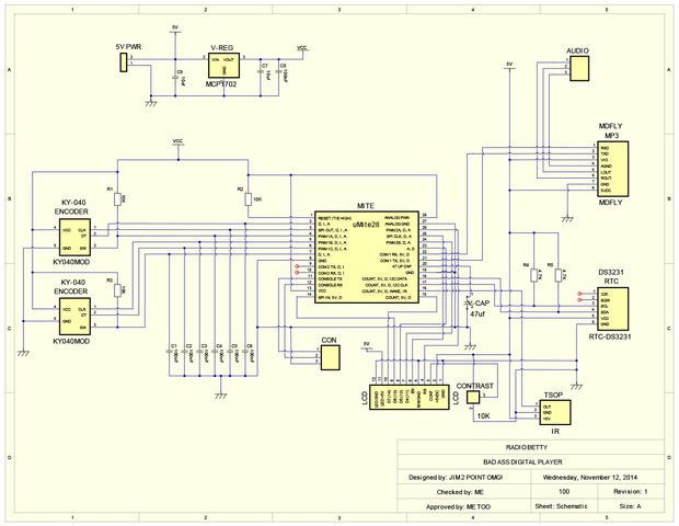
The circuit was first laid out on a breadboard in order to test the functionality of each of the modules being used and test the software, after which I used Autotrax Dex to create the schematic of the unit. As you can probably tell by looking at the schematic, this was my first attempt at using a pcb design program to make a project. It’s not NASA quality by any means, but it does work.
Step 3: Lets make a PCB
Once I spent a little time with AutoTrax Dex, I decided to take the plunge into having my very first PCB commercially made. This program took a bit of learning, like anything else, but proved to be a great experience for a first time and has given me the confidence that this is the way to do things going forward.
Step 4: From China with Love
AutoTrax Dex created all the files needed to have a PCB made. I used Itead Studios in China as their pricing was incredibly reasonable. It took about 3.5 weeks to get the board back and you can bet I was nervous about this working out of the box. I scoured the Interweb for information concerning drill hole sizes for the different components used and once the boards came, I immediately plugged in all the parts to make sure they fit. While waiting for the boards, I couldn’t stop thinking about part leads not fitting into their holes. Thank goodness, it all worked. Thanks Interwebs!!!
Step 5: Let’s stuff this thing
It only took about 45 minutes to get everything soldered up and powered. I must have the luck of the Irish as this little unit fired right up.
Step 6: Front Panel
My day job puts me in a well equipped sign shop so I took advantage of the situation and used some scrap acrylic and digital printing to create the front panel for the “radio”
Step 7: Front Panel 1
A piece of 1/8″ black acrylic was laser cut to accept the 2004 lcd display, the two encoders and the TSOP4838 infrared receiver. I used 4-40 flat head screw and by using 3 stacked nuts as spacers, the LCD wound up flush to the face of the acrylic.
Step 8: Front Panel 2
LCD display mounted to front panel. This worked out nicely using the 3 nuts as spacers.
Step 9: Front Panel 3
The front panel with all the parts installed.
Step 10: Front Panel 4
A piece of .040 clear acrylic was used to make the front panel graphics. I created the print in Photoshop using a “parchment paper” graphic and added the type and floral graphics to that. The design under “Radio Betty” has a hole cut in the print in order for the infrared receiver to “see”. The only holes that go completely thought the acrylic are for the two encoder shafts. The infrared and LCD area are only cut out of the print, not the acrylic.
Step 11: Front Panel Done
All put together and ready to install in the wood cabinet.
Step 12: Time to cut some wood
I used 3/4″ poplar for the visible parts of the cabinet and plain plywood for the speaker faces as they would eventually be covered up and not seen.
Step 13: The Cabinet 1
The fronts of the four upright panels were shaped using a 3/8″ round over router bit on each side to create a full half round, after which a bit of sanding with 220 grit sandpaper made for a smooth finish. The two inside uprights were slotted on a table saw to fit the front panel between them.
For more detail: An “Antique Radio” Christmas Present
- What is the main function of the Radio Betty project?
The device functions as an MP3 player disguised as an antique radio to play old time radio programming. - How was the circuit initially tested before making the PCB?
The circuit was first laid out on a breadboard to test the functionality of each module and the software. - Which software was used to create the schematic design?
The author used Autotrax Dex to create the schematic after testing on a breadboard. - Where were the PCBs manufactured and how long did shipping take?
The boards were made by Itead Studios in China and took about 3.5 weeks to arrive. - What materials were used to construct the front panel?
The front panel uses 1/8" black acrylic for mounting parts and .040 clear acrylic for the printed graphics. - How was the LCD display mounted flush to the front panel?
The author used 4-40 flat head screws and three stacked nuts as spacers to mount the LCD flush. - What type of wood was used for the visible parts of the cabinet?
The author used 3/4" poplar for the visible parts of the cabinet. - How were the upright panels of the cabinet finished?
The fronts were shaped using a 3/8" round over router bit and sanded with 220 grit sandpaper.
