
This PIC microcontroller EEPROM project saves the temperature from an LM35DZ IC to the PIC’s internal long term data storage area. The project follows on from the last project using the virtually the same hardware.
It stores temperature readings internally at regular intervals until full and after this it turns on the LED. The LED is really just for showing that something is happening and in a real data logger you would not use it.
Note: This project is not optimized for power consumption so the best way to use it is powered from a power block. The current consumed is about 13mA (LED off) 16mA (LED on at end). If you want to use a battery use a rechargeable PP3 and do not attach the LED.
The 12F675 may not the best PIC microcontroller to use for low power data logging and a better choice would be the 16F88 as it can change its internal oscillator on the fly going into slow (current saving) mode. But you could use the 12F675 with a slow external 32kHz crystal.
At every ADC reading the LED is flashed briefly and when you select a 500ms reading interval you can see the readings being taken. When 64 readings are accumulated the LED is lit permanently – showing that the data store is full.
Note: For this chip you only get to store 64 results as you need to store an unsigned integer for every ADC result and this takes 2 bytes so 128 Bytes/2 = 64 results.
To erase the internal EEPROM hold the button and cycle the power – this flashes the led 6 times indicating erase (normal startup flashes the LED 3 times).
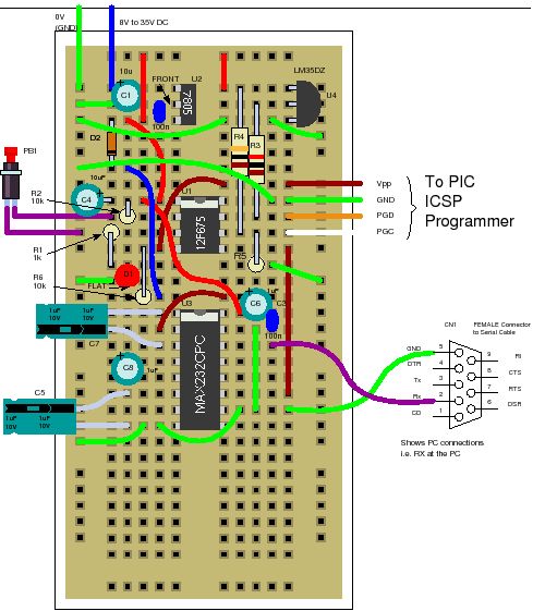
Solderless breadboard
The solderless breadboard and circuit diagram are nearly the same as used in the previous project so if you have already built it you don’t need to do any more. Just add the blue wire, D2 and R6.
Circuit diagram
Setting GP3 low causes a reading update rate of half a second (for debug) while setting it high causes a reading update rate of approximately 30 minutes. So for the full 64 readings you get temperatures measured and stored every half hour over a 32 hour period. Note: The measurement time is not calibrated so it won’t be exactly 30 minutes. Note: The circuit/software is not optimized for power usage so you should use a power block to give the circuit power otherwise a battery would be drained fairly quickly.
