Summary of AmpStrike – Battery Powered Bench Power Supply
### Summary This article describes a battery-powered bench power supply featuring a discrete linear voltage regulator and an STM32F103 microcontroller. The regulator uses a pass transistor, op-amps, and a comparator for precise voltage and current control. Current sensing is handled by a MAX4080 amplifier with a multi-resistor shunt. The microcontroller manages the entire system, including a switching pre-regulator, LCD display, rotary encoder, and optional communication modules like Bluetooth or Ethernet via UART.
Parts used in the Battery Powered Bench Power Supply:
- Q1 pass transistor
- U5A op amp
- U5D comparator
- MAX4080 current sense amplifier
- Shunt resistor (composed of 10 smaller resistors)
- U5B and U5C op amps
- Filtering resistors and capacitors
- Two 10uF ceramic capacitors
- Protecting diode
- STM32F103 microcontroller
- LCD display
- Switches
- Rotary encoder
Linear Voltage Regulator
The power supply runs on a linear voltage regulator built on discrete components. The design of the linear regulator was inspired by the user Amspire from the EEVblog forum. The basic idea is that the Q1 pass transistor and U5A op amp act in a classic voltage regulating loop. U5A gets feedback from the output voltage and acts on Q1 in such a way that the output voltage equals the reference voltage on the inverting input. U5D acts as a comparator and switches the base of Q1 low to set the output voltage to 0V. It acts as a current limiter which is quickly switching on and off the output to maintain the set current limit. The current drawn by the load is measured by a MAX4080 current sense amplifier using a shunt resistor which is made up of 10 smaller resistors to get better power dissipation and current capability. U5B and U5C combined with the adjacent resistors and capacitors act as filters to smooth out the PWM signal from the microcontroller. The output contains two 10uF ceramic capacitors, a protecting diode and a small current source that acts as a small load to make the power supply more stable.
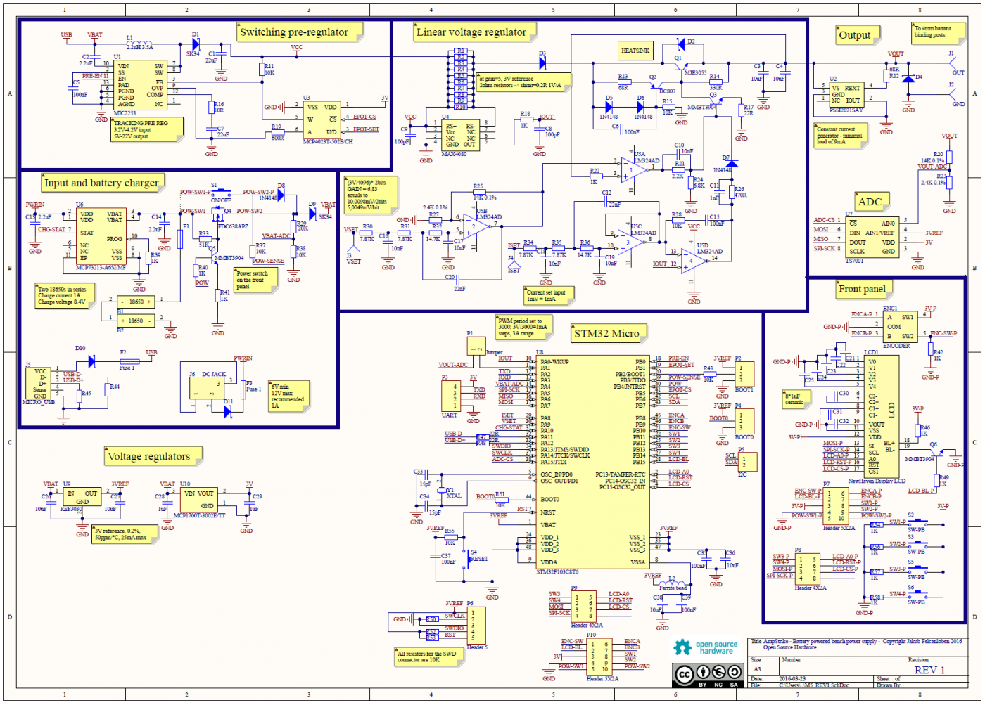
Microcontroller
The entire voltage and current limit is controlled by a STM32F103 microcontroller. It might seem as a bit of an overkill for such a project, but actually these microcontrollers are quite cheap and they have the 12 bit PWM required for this project. The STM32 controls pretty much the entire power supply, including the switching pre-regulator, the output voltage and current limit and the front panel with an LCD, swtches and a rotary encoder used to set the desired values. Some USB capability can be added in the future. The user can also make use of the UART connector to plug in some bluetooth or Ethernet modules (with some additional code).
For more detail: AmpStrike – Battery Powered Bench Power Supply
- What components form the linear voltage regulating loop?
The Q1 pass transistor and U5A op amp act in a classic voltage regulating loop. - How does the circuit limit current?
U5D acts as a comparator that switches the base of Q1 low to set output to 0V and quickly switches on and off to maintain the set current limit. - Which component measures the load current?
A MAX4080 current sense amplifier measures the current drawn by the load. - Why is the shunt resistor made of 10 smaller resistors?
They are combined to achieve better power dissipation and current capability. - What is the function of U5B and U5C?
Combined with adjacent resistors and capacitors, they filter and smooth out the PWM signal from the microcontroller. - How does the design ensure stability at the output?
It includes two 10uF ceramic capacitors, a protecting diode, and a small current source acting as a load. - Why was the STM32F103 chosen for this project?
It is cheap and provides the necessary 12 bit PWM required for the project. - Can the power supply be connected to external networks?
Yes, the user can plug in Bluetooth or Ethernet modules using the UART connector.