Summary of A recording studio for the PIC32
This project is a miniature recording studio built around the PIC32 microcontroller, allowing users to record, playback, and layer sounds from piano, guitar, bass, drums, and a microphone for custom sounds. It features an interactive menu and controls, with synchronization for simultaneous playback and recording. The system supports around 2 seconds of sound recording at 8 kHz sampling rate for up to four beats, balancing sound quality and memory usage. The hardware includes button inputs, microphone analog audio input with amplification and filtering, and speaker output through a DAC. Software uses SPI and ADC, with sound data stored in arrays generated via MATLAB and audio editing.
Parts used in the Miniature Recording Studio for the PIC32:
- PIC32 Microcontroller
- Push Buttons (10 total: 8 for keyboard octave, 2 for menu control)
- Microphone (with voltage divider and non-inverting amplifier circuit)
- Analog-to-Digital Converter (ADC) input for microphone
- Speaker connected through audio socket to DAC output
- Digital-to-Analog Converter (DAC) on PIC32
- TFT Display for menu and status indications
- Voltage divider and RC low/high pass filters for microphone signal conditioning
- Non-inverting amplifier (gain ~100) for microphone signal
- Wiring, resistors, capacitors for button circuits with pull-down resistors
- SPI Communication Interface (for DAC output)
- Oscilloscope (used for testing/debugging sound signals)
- Breadboard for mounting circuitry
Introduction
We built a miniature recording studio using the PIC32 that allows the user to record a short soundtrack, play it back, then layer on additional sounds. We chose to support sounds for three tonal instruments: piano, guitar, and bass, as well as eight unique drum sounds. The user can play a full octave on each of these instruments, but not flats or sharps. This design choice balances the limited capabilities of the PIC32 with giving the user the ability to create complex sounds. We also have a microphone that the user can use to record custom sounds. The user can use the recording and playback modes separately. While recording, the notes played by the user are saved to be played back, and in playback mode the recorded sounds are played through a speaker to the user. The user can also playback and record at the same time. The system synchronizes the two if they are happening at the same time so that the playback begins while the system starts recording. If the user starts recording during a playback, the current playback finishes, and the recording starts at the beginning of the next playback. If the user starts recording while not playing back, there is a countdown from 3 to allow the user to prepare before the recording starts. In addition to the progress bar, which shows the progress through a recording or playback, we also have a small red circle that displays when we are recording. There is also support for deleting the current recording allowing the user to start a new song without resetting the whole studio. The recording studio also has a visual component in a menu that indicates to the user what instrument they are using, toggling playback mode, and deleting the current recording. Recording mode is toggled by a separate button which starts recording with any of the instruments or the microphone mode selected. The recording studio can save about 2 seconds of sound, which allows the user to record a full four beats at 120 beats per minute. This gives the user enough time to create interesting layered sounds.
High level overview
Like most projects in Microcontrollers, we begin by breaking the overall task into smaller ones. Also like in previous labs, we will place the smaller tasks in threads so the system can be responsive and multitask successfully. The high level tasks are as follows:
- Display: We wanted a menu for the user to toggle between the playable instruments, manage their recording by toggling playback or deleting the recording. The display thread has a variety of static text, a cursor that moves when the mode button is pushed, and a progress bar that shows how far along you are in the recording loop.
- Buttons: Our project was motivated by electronic keyboards which had recording functions, and we wanted our project to be able to play like a keyboard by having nice buttons that were playable like an electronic buttons. The buttons have 30 ms debouncing, like our lab 2 keypad. Each button was then routed to a pin on the board.
- Playing Sound: We needed our board to be responsive to button pushes and play realistic sounding notes instantly. We play sound one increment at a time, in an ISR, with sound output via SPI, like lab 2 also.
- Recording user via microphone: We need to be able to have clean audio from the user with an easy interface for recording. We had to high and low pass filter the microphone audio, as well as amplify it so it could be audible and clear.
- Recording instruments to play back through looping: Loop functionality also needs to be intuitive for the user.
Hardware design
There were 3 major hardware components involved in implementing our project successfully: the button, microphone setup, and speaker circuitry.
The Button Setup:
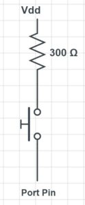
- We used push buttons for 2 main purposes. 8 buttons were used as our keyboard so the user could play 8 sounds (an octave) for each instrument. 2 more buttons were used in the user interface, one was used solely to toggle the menu options while the other alternated uses between toggling recording and playback or selecting delete depending on the current mode. We enabled pulldown for all the appropriate pins on the board, as we’ve done in previous labs. The schematic below depicts the schematic for connecting a single button to the board. A similar circuit was used for all 10 push buttons.
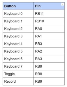
Initially when we were trying to find 10 available I/O pins on the PIC32, we struggled a lot. We didn’t pay enough attention to our pin assignments and unknowingly connected 2 buttons to pins that were in use by the TFT. Thus, these buttons were being read as always pressed and our project was outputting constant noise. At first we mistook this sound for actual noise and we thought about trying to filter the noise. However, after we realized our error we essentially tried every possible pin assignment and finally reached a satisfactory pin assignment, as listed below. The keyboard buttons are numbered left to right as they would appear from the user’s perspective.
The Microphone Setup:
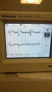
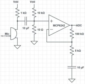
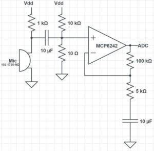
We used a microphone which we acquired from lab. The microphone was set up to receive input sound from the user and feed it to the board through ADC. The output of the microphone was too small, so we implemented a voltage divider and non-inverting amplifier on the output of the microphone before wiring it to ADC. Since the intended use of our microphone was for a person’s voice, we chose appropriate RC time constants to allow those frequencies to pass. For our amplifier, we started out with a gain of 20, but we chose to increase our gain to 100 so the waveforms would reach their full amplitude from -1.5 to 1.5 volts. This did cause some clipping to occur when sounds were very loud into the microphone, but as long as the mic is used from a few inches away, this is not a problem. An oscilloscope screen depicting the unamplified and amplified microphone output is pictured below. This image does show some clipping because we tested the mic by tapping the mic head, which is very loud in the mic.
We were getting an audible amount of noise from our microphone when we recorded its sound output. Our first attempt to fix this was to fix the wiring and isolate the microphone from the power cables as much a possible. Unfortunately this didn’t significantly reduce the noise. We also tried various high-pass and low-pass filters outside the typical speaking voice range to try to eliminate noise. Yet the best result we could achieve was an odd clicking sound in place of the noise. When we fully tested our projects functionality, we discovered the in comparison to the sound from the various instruments, the noise from the microphone recording was very unnoticable, so we decided to leave it as is. The schematic of our finalized microphone circuit is depicted below.
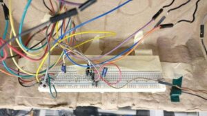
Our breadboard with the completed circuit is picturized below, however since this picture was taken after the breadboard was mounted under the Recording Studio, it’s hard to see clearly.
The Speaker Setup:
The speaker was connected to a socket which was connected to the output of the DAC, similar to the setup in lab 2. The left and right sides were shorted to produce mono audio. A schematic of our audio socket connection is depicted in Appendix C.
Software design
To create our sounds, we saved sound files as a single array and wrote the data of the array to the built-in DAC of our development board. The DAC output was connected to the speaker as outlined in the hardware design section. The vast majority of our code was in the file brainstorm.c. In this file, we get input from the user and then play the appropriate sounds using SPI in an ISR. This separation of code into header files made it easier to change our sound files during development as we found ourselves frequently editing the sound array. The following subsections describe in more detail the purpose of each file and how they work.
Sound file generation
We searched YouTube for people playing C major scales with guitar, piano, and bass. These notes were then clipped to a relatively short length (about 0.05 seconds), and then put on repeat for playback on the device. For the drums, 8 different diverse drum sounds were selected, about 0.5 seconds each, and when in drum mode they are played once.
The sound files were clipped using the audio editor audacity, and then they were made into header files in MATLAB, after resampling to 8khz. 8 khz was selected to minimize storage space usage on the PIC. The MATLAB script then adjusts the range from [-1,1] to [0,256), and rounds to the nearest int to fit the unsigned chars range.
Header Files
Our project includes 2 different header files. The project plays the sounds as defined in the header files.
sounds8again2.h:
This header file is a MATLAB generated file which contains a very large array called ‘sounds’ of unsigned chars, stored in flash memory. Our project consists of 4 different instruments , each with 8 different sound options. Thus, we have 32 sounds which need to be stored. Our approach was to use a MATLAB script to sample the sounds at the right frequency and scale them down to chars. Then we compiled every single sound in a single array, ordered first by ‘mode’ or instrument, then by button on the keyboard. ‘sounds’ is that array. As you can tell by the name, it took us quite a few iterations of this header file to generate sounds that we were satisfied with.
wavLocNew2.h:
This header file is also MATLAB generated and contains 3 things.
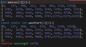
- wavStart: a 2 dimensional array of ints which is also stored in flash memory. This array has a size of 4, representing each instrument mode, where each element contains an array of size 8, representing the 8 different keys. Each element of this array contains the beginning index of the respective wave sound in the larger ‘sounds’ array. Thus, when a user presses a key for a certain instrument, we know where the sounds for that key are stored in the large array and can play it back accordingly.
- wavLoc: a 2 dimensional array the same size as wavStart that is not stored in flash memory. This array contains the current location of the playback of that specific sound. This array is initialized to be identical to wavStart because before any key has been pressed, all the current locations are at the beginning of the sounds. For example, when a person presses a drum sound, as the sound is played, wavLocs will track the current location in the ‘sounds’ array and indicate when the drum sound has completed, signaling the sound to stop (since drum are only played once while other sounds are played on a loop continuously).
- wavLength: a constant value declaration indicating the length of the entire ‘sounds’ array. In most situations, to determine if a sound has ended, wavLocs can be compared to the starting index of the subsequent sound. However, when trying to check if the last sound of the last instrument is complete, there is no subsequent sound, so wavLength is used instead.
Code Breakdown
brainstorm.c
This file does all the computation for our project. We separate it into two threads, an ISR, and main which does some initialization and schedules the two threads. The first thread, the button thread, is responsible for reading input from the user in the form of button presses and then setting the control values appropriately. These control values are used in the ISR and the draw thread to produce the sounds and display the state of the recording studio. We choose to sample our sounds at a rate of 8 kHz, meaning that we also had to trigger the ISR at 8 kHz. This rate gave us a good balance of sound quality and recording length. With a higher sampling rate, we had slightly better sound quality but at the expense of recording length. Because the length of our recording is limited by memory, a faster ISR means that we fill the array faster. Choosing 8 kHz over say 44 kHz gave use more than five times longer to record which is very significant compared to the lost sound quality which was minimal.
Outside of each of these functions, we declare several global variables and defines, which have the following purposes:
buffer,arrow, andgetReadyare character arrays used to store strings that will be written to the TFT displayreadyVaris set high before the studio starts recording, used to give the user adequate time to preparedrumPlayis used to track whether or not a drum note has been played to completionarrPosandoldArrPosare used to place the arrow in the menu and also used to determine which menu option is currently selected by the userrecordingandplaybackare state variables that indicate whether the system is currently recording or playing back respectivelyoldPlaybackandoldOldPlaybacktemporarily store old values of playback to help us with printingsoundOutstores the value that is sent with SPIpressedand oldPressed are used to determine which buttons are pressed and for debouncinguserWavis used to read values from the microphoneiandjare used for iterating through for loopsmodedescribes which menu option is selectedrecordWav, rInd, and rWavSize are used for storing and iterating through the sounds recorded by the user- the
PIN_xdefines gave us a convenient way to change which external pin was connected to each note - the other define statements simplified initializing the ADC input and the SPI output
Within brainstorm.c …
ISR
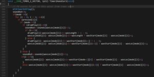
The main task of the ISR is to write the correct output value to the DAC using SPI, however what is involved in this task varies depending on a number of factors, meaning that the code has a lot of if and else statements to determine what needs to be done. First, we clear the interrupt flag, and set soundOut to 0 to remove the data from the previous write. Next, if mode is less than 4, indicating that one of the instruments is selected in the menu, we iterate through the pressed array to determine what buttons are currently pushed. If the mode is 0, 1, or 2, and the button is pressed, we add the element at [waveLoc[mode][i]], our current position for the given sound, in sounds, and then increment waveLoc[mode][i] appropriately. We also shift the output of sound one bit left to amplify the volume of the system. The increment is made slightly more complicated because we store all of the sounds as a single array, but we essentially check if we have reached the end of that sound and if so reset to the beginning, otherwise increment by one. We have to do essentially the same thing if we are in mode 3, however we only want to do this if the drum sound has not completed already. This is because for the drums we only want to play the sound once for each button hit. Additionally, when we increment wavLoc for the drum sounds we must also set drumPlay[i] when we reset the sound, indicating that we should not play it again. Additionally, we shift the drum sounds an extra bit left because the raw sound files were quieter than the tones. All together, here is the block of code:
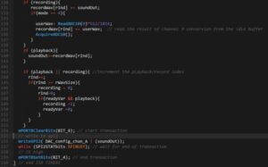
The above blocks of code are how we set soundOut based on button presses, but the ISR must also take action depending on the values of recording and playback. If we are recording, we need to add the result of pressing buttons, and if we are in user mode we add the results of reading from the microphone. We divide the reading by 2 to put it closer in volume to the other sounds, while still allowing it to be heard. If we are currently playing back, we just need to increment soundOut but the recording wave. The final condition we check applies if we are either recording or playing back. If we are doing either, we need to increment rInd. If it reaches the maximum size of the record wave, we reset it to 0 and also set recording to 0. Finally, if we reached the end of the array we also check if readyVal and playback are set. If they are that indicates that we need to record in the next playback so we set recording and reset readyVal. The final task of the ISR is to actually send the data set in soundOut. We do this by setting the chip select low (it is active low), giving the command to write the data, waiting for the data to be sent, and then setting chip select high again. Put together, the code becomes this:
Throughout the testing and debugging of our project several changes were made to original code to arrive at the final product described above. One bug we had was that drum sounds seemed to start at random points in the sound array. We found that the cause of this was that we were incrementing the wave location even when the drum sound had already been played. We also had an issue where the recorded sounds would get louder as you layered additional recordings even when there were no additional sounds. We found that the problem was that we checked if we were recording and playing back in the wrong order, so we were accidentally doubling the recording wave. We also had to make small changes to how incrementing worked after we switched our design for have all of the sounds in a single array.
Button Thread
The main job of the button thread is to read the input pins connected to the buttons and set the control signals for the ISR and the draw thread. It also writes to the TFT when the user should prepare to start recording. We also however have to debounce the buttons. Instead of using a state machine like we did in Lab 2, we opted for a simpler implementation for this project which was easier to use and also gave reliable results when user testing. For each button, we read the ports at the beginning of the thread, then yield for 30 ms, giving the buttons enough time to settle if they were bouncing. If the reading after the yield is the same as before, we consider this to be the state of the button. If it is different, we leave the value unchanged. For the recording and menu buttons however, we only want to register a press if the button went from low to high because we want each press to be registered exactly one time, so we only set pressed if the reading is greater than the old reading.
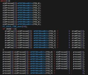
We also set drumPlay based on reading the ports. In the same way that we only want to read a menu button press once, we want to set drumPlay to 0 exactly once, each time the button is pressed while in drum mode. If the button is not pressed again, we leave it unchanged.
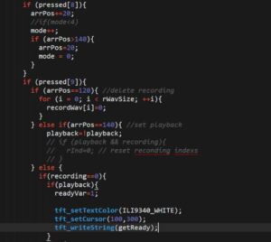
Next, we have to set control signals based on the pressed buttons. If the menu button was pressed, we mode and arrPos, looping back if they hit their maximum values (ie the button was pressed with the last menu option selected). Next, we set the control values based on if the record button is pressed. The record button can have a number of different functions. If delete is selected in the menu, it sets the entire record wave to 0’s, effectively deleting the recording. If playback is selected in the menu, it toggles playback, either to on or off. If neither of these are selected in the menu, then pressing the record button should do one of two things. If playback is on, then is should set readyVar and print “Get ready!” in the bottom right of the screen. This is eventually translates to setting record once the current playback has completed. If playback is not on, then pressing record while not already recording starts a countdown from 3 until recording starts. We first set readyVal to 1, draw each number, yield for 400 ms, then draw over it in black and draw the next number. After erasing the 1, we reset readyVar and turn recording on. Lastly, we display the recording status bar or the get read text with some prints, if in the correct playback or recording mode.
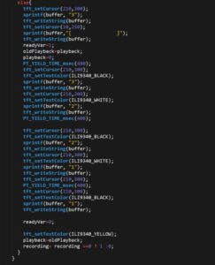
While debugging this thread, our first issue was fixing it so that drums would only play once. Our original design didn’t account for holding down the drum button. This resulted in us adding the drumPlay array to our design, which also required some changes in the ISR. We also had to make modifications as we changed the way we wanted playback and record to interact. Initially they didn’t synchronize automatically, so you could start recording at any point in the playback. We decided that this was more of a limitation than a feature because in almost all circumstances the user would want all of the recordings to line up. This led to having a timed “get ready”, where the progress bar would stop and after a short period of time the recording and playback would start. This also make it difficult to synchronize the recording and playback because it was difficult to anticipate when the recording would start. The system that we have now improves upon this by using the readyVar. This allows the current playback to complete and then the recording begins immediately with the next playback. This allows the user ample time to prepare to play after hitting record and also allows them to get a feel for the tempo of the playback and layer onto it seamlessly. Each of these progressive design changes required changed with how we handled the pressing of the record button and took a significant portion of the time we spent debugging. We also spent significant time mapping the right input pins to the correct indexes of pressed. While the PIN_x defines made modifying the code easier, it added a level of abstraction that made it difficult to wrap our heads around why pressing which button created the tone that it did. We kept thinking that PIN_0 was the leftmost button when really PIN_0 corresponded to an A (the pitch) and we had to connect it to the input pin connected to the leftmost button.
Main
We only use main to do a few initializations that only need to be completed once. These set up the SPI and ADC for use in the other pieces of the program, write the menu options to the TFT, configure our input pins for use with the push buttons, and initialize the timer for the ISR. After doing these initializations it schedules the protothreads to run in round-robin style. First, we initialize the timer 2 with a refresh rate of 8 kHz, (we give it the value 5000 because it divides the clock rate of 40 MHz by the input value), and configure it to call our ISR when it refreshes. We also have to clear the interrupt flag initially.
OpenTimer2(T2_ON | T2_SOURCE_INT | T2_PS_1_1, 5000); ConfigIntTimer2(T2_INT_ON | T2_INT_PRIOR_2); mT2ClearIntFlag();
Next, we set up the SPI channel to allow us to write the soundOut array to the DAC. We connect SDO2 to pin RB5 using PPS output, and set the chip select pin for SPI to be digital output and set it high. We then open the channel in the standard, non-framed mode.
PPSOutput(2, RPB5, SDO2); mPORTBSetPinsDigitalOut(BIT_4); mPORTBSetBits(BIT_4); SpiChnOpen(spiChn, SPI_OPEN_ON | SPI_OPEN_MODE16 | SPI_OPEN_MSTEN | SPI_OPEN_CKE_REV , spiClkDiv); The setup for the button pins is next. This is simple as it just involves setting them to digital output pins and enable built-in pull down resistors to avoid floating states. mPORTASetPinsDigitalIn(PIN_3 | PIN_2 | PIN_5 | PIN_6); EnablePullDownA(PIN_3 | PIN_2 | PIN_5 | PIN_6); mPORTBSetPinsDigitalIn(PIN_0 | PIN_1 | PIN_4 | PIN_7 | PIN_8 | PIN_9); EnablePullDownB(PIN_0 | PIN_1 | PIN_4 | PIN_7 | PIN_8 | PIN_9);
We also have to set up the ADC for reading from the microphone. We first close the channel to ensure it is off before configuring. We then configure it to read from analog input, not in automatic mode. This means that we have to call functions to read from the ADC when we need it which is fine for our purposes. We then reopen the channel and enable it.
CloseADC10(); SetChanADC10( ADC_CH0_NEG_SAMPLEA_NVREF | ADC_CH0_POS_SAMPLEA_AN11); OpenADC10( PARAM1 , PARAM2 , PARAM3 , PARAM4 , PARAM5 ); EnableADC10();
The final step before scheduling the threads is to initialize the TFT. First we assign the permanent values to getReady and arrow for use by other threads. We then initialize the TFT, rotate it give us the desired orientation, and write the different menu options down the screen.
sprintf(arrow, " >"); sprintf(getReady, "Get ready!"); tft_init_hw(); tft_begin(); tft_setTextColor(ILI9340_WHITE); tft_setTextSize(2); tft_fillScreen(ILI9340_BLACK); tft_setRotation(0); tft_setCursor(40,20); sprintf(buffer,"piano"); tft_writeString(buffer); tft_setCursor(40,40); sprintf(buffer,"guitar"); tft_writeString(buffer); tft_setCursor(40,60); sprintf(buffer,"bass"); tft_writeString(buffer); tft_setCursor(40,80); sprintf(buffer,"drums"); tft_writeString(buffer); tft_setCursor(40,100); sprintf(buffer,"user"); tft_writeString(buffer); tft_setCursor(40,120); sprintf(buffer,"delete"); tft_writeString(buffer); tft_setCursor(40,140); sprintf(buffer,"playback"); tft_writeString(buffer); tft_setCursor(130,140); sprintf(buffer," off"); tft_writeString(buffer);
The final step is to initialize and schedule the protothreads.
PT_setup(); PT_INIT(&pt_draw); PT_INIT(&pt_button); while (1){ PT_SCHEDULE(protothread_draw(&pt_draw)); PT_SCHEDULE(protothread_button(&pt_button)); } There were very few changes made to main because we have done most of the initializations in earlier projects, so we were familiar with the procedure. There only part that changed from our original design was which pins had to be initialized on port A and which had to be initialized as port B.
Results: the implementation process
The most extensive testing happened with testing the sound files, which were loaded on the board and played aloud and their quality was assessed. We clipped and corrected our indexing to make the sounds sound the best to our ears (the difference in audio quality is hard to hear in our snapchat videos, however). This was the meat of the debugging. We had some small issues getting the menu and loading bar to work, and this was just debugged with the usual prints to the TFT.
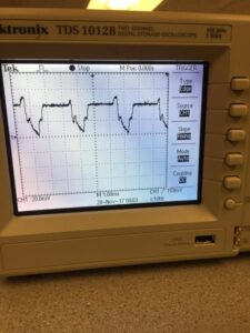
There was also some oscilloscope testing. This was the original pointer to us that our clicky noises that we were getting were indexing issues, because of the way the sudden dropoff occurred in wave. We also had an issue with too much audio played at the same time, and clipping out.
Here is a badly indexed wave form on the oscilloscope:
We did not have any safety constraints in our design. Even at max volume, the device is not able to play music that is that loud on ordinary household speakers, so there is no risk to hearing loss.
We believe that our device is usable to people who have a sense of hearing, and good motor control of their fingers. The buttons were hot-glued onto stiff cardboard to avoid their bouncing or jiggling when pushed, and they are very stable.
Conclusion
Overview: Expectations and Results
As a whole, we were very pleased with the resulting project. We were pleasantly surprised that we were pretty much able to provide our user with almost all the functionalities initially laid out in our proposal. At first we did expect that we would be able to complete this project in its entirety. However, as we progressed, we had to modify our expectations a bit. While dealing with the large amount of sound files as well as playback ability, we began running into a roadblock with the limited memory space on the microcontroller. We found that only sampling at 44kHz would make our keyboard sounds nice enough that the different instruments and notes would be recognizable. This sample rate limited our recording capability to ~0.25 seconds and completely erased the possibility of incorporating a user mode where the user could add their own sounds as well as a microphone input. After consulting Prof. Land and finding a bug in our code, we found that we could sample at a significantly slower rate while still maintaining audio quality. This allowed us to provide upto ~2 seconds of recording capabilities. At 120 bps, this is just about 2 measures of music, which we found was just enough to allow the user to experience the overlay capabilities and build up a nice music track. Once we figured out this error we also had the chance to incorporate a microphone to allow realtime user input to the current audio track when recording. The only feature we did not get to implement in time for this project was the advanced user mode where the user could store new sounds the had created and play them back with the press of a button, so that such sounds could be continuously incorporated in different music tracks. Given that we already maxed out our memory with our recording storage, we couldn’t add the advanced user mode without detracting from the recording, given our time constraints. In the future, if we were to do this project again or improve upon it, we would love to incorporate this advanced user mode to expand the capabilities of the Recording Studio. We could do this by expanding the memory of the microcontroller, perhaps by using an SRAM along with the existing flash memory. We also would find it useful to include a metronome option to keep tempo so the user can layer tracks more confidently, as we found keeping tempo between different overlays to be difficult when using our project. Additionally, we were able to implement a better user interface than we had additionally planned by including progress bars to keep the user aware of how far they are into the playback/recording as well as various countdowns and visual signals with regards to recording/playback to make the Recording Studio user-friendly. In another iteration of this project we would hope to improve our user interface even more, perhaps by using a touch-screen display to avoid the hassle of the toggle buttons, and possibly by making our menu and interface appear more appealing. As people who enjoy and appreciate music, from a usability perspective, we thoroughly enjoyed making music, albeit short lengths of music, with our Recording Studio once it was complete. We are very proud of our results and satisfied with what we were able to achieve. Any further improvements we would choose to make would only optimize our current setup and expand its potential.
Standards
We found no applicable standards to which our design had to conform to.
Intellectual Property Considerations
While there are many similar keypad/recording overlay products available to consumers and such, in our research we found no proof that our project infringes on any existing patents/copyrights. We do not intend for our product to be patented in the future. All of our sources for audio files are included in Appendix F. We borrowed the structure of our code and based some of our circuitry upon previous labs also cited below through the ECE 4760 course website. Our project also made use of the PIC32 Standard Peripheral Library and the Protothreads library.
Ethical Considerations
In accordance with the IEEE Code of Ethics, we designed our project with the safety of the user in mind. At this time, our project doesn’t pose any threat to the “safety, health, and welfare of the public.” To make the project user-friendly, we used a sturdy cardboard box such that the buttons were mounted on top, along with the TFT display, and all the wiring and circuitry was concealed under the box, not easily accessible or harmful to the user. Throughout the design of our project, all group members have made every effort to ensure that our project is compliant with the IEEE Code of Ethics and is safe in both design and in practice, to the best of our knowledge. All outside sources/influences on our project have been appropriately cited in Appendix F. We believe the biggest health risk our project could pose, would be if a user tries to play back sound too loudly. If anything, we simply recommend that the audio output of our device should be heard through speakers/headphones with volume control so the user can control the volume of the sound output without any potential impact on their hearing. However, as we don’t currently intend to reproduce our project for consumers, we don’t see this being an issue. At any point in the future, if a violation of the ethics code or any harmful effects of our project are brought to our attention, we we will address the issue swiftly and properly.
Legal Considerations
As stated in the Intellectual Property Considerations section, we have found no evidence that we are infringing on the intellectual property of any other person. At this point, we have no legal considerations/restrictions to consider as far as we know.
Schematics
Source: A recording studio for the PIC32
