Each of the output lines of a ‘508A microcontroller can deliver a maximum of 25mA.
What does this mean?
It means any device connected to the line must take 25mA or less.
If it takes more than 25mA a buffer transistor (also called an amplifying transistor) must be used and this will be discussed in a moment.
However, if it operates on less than 5v, and requires less than 25mA, a current-limiting resistor must be included.
A typical device that requires less than 5v and draws less than 25mA is an LED.
A LED must be supplied with an exact voltage for it to operate correctly. Because it requires LESS than 5v, a dropper resistor (current limiting resistor) must be included in series to “take-up” or “absorb” or “interface” the LED to the output line. Working out the value of the current-limiting resistor requires some mathematics but this is very easy when you know how. 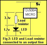
25mA
The current taken by a device is called the LOAD CURRENT. Twenty-five milli-amp is not very much in electrical terms but in electronic terms, it is amazing what can be driven. 25mA is 0.025Amp and this is not sufficient to drive a motor or globe but there are a number of devices that can be driven.
1. LEDs (Light Emitting Diodes) require up to about 25mA for full illumination.
2. Piezo diaphragms require very little current and can be driven directly from an output line.
3. Low-current relays can be driven directly provided they operate at 25mA and 5v. If more than 25mA is required, a driver transistor (also called a buffer transistor or buffer stage) will be needed. The specification for an output line is 25mA @ 5v. In other words the output line has an output voltage of 5v and the maximum current that can be delivered by it is 25mA.The output line will, in theory, deliver more than 25mA but the transistor (in the chip) delivering the current may be damaged (overheated) if a higher current flows. The current delivered by the output line is determined by the resistance of the device (or devices), connected to the line.
The simplest device is a resistor as shown in fig: 1.
If the resistance of the resistor is too low, more than 25mA will flow. If the resistance is high, less than 25mA will flow. The current flow is not determined by the chip but by the value of the resistor. The resistor is called the LOAD RESISTOR or simply the LOAD.
THE VALUE OF THE LOAD RESISTOR
The resistance of the load resistor is worked out using Ohm’s Law. We know the voltage on the output line is 5v. This is V in the formula. The max current available is 0.025A = I in the formula. Ohms Law states: I = V/R (Current equals volts divided by resistance). This equation can be re-arranged as:
R = V/I
Putting the two values into the equation produces:
R = 5/.025
= 200
= 200ohms. A 200 ohm resistor connected to an output line will allow 25mA to flow when the output is HIGH. This is only a theoretical explanation as a resistor on an output line will not perform any function! It won’t do anything by itself except get slightly hot. But a resistor will perform more than 20 different functions, depending on where it is placed in a circuit and the value of the components around it. In our first example below, a resistor is added in series with a LED so that the LED will take a maximum of 25mA. The purpose of the resistor is two-fold. Firstly it allows the LED to create a characteristic voltage across it of 1.7v (for a red LED) and secondly it has a value so that 25mA flows through the LED. The resistor will have 5v on one end and 1.7v on the other. These voltage are provided by the chip and the LED and the resistor has nothing to do with creating them. The resistor simply allows a certain amount of current to flow, depending on its value, (25mA) and that’s the value worked out above.
A point to note: The ‘508 has 5 output lines and if all the outputs are delivering 25mA, the total output for the chip will be 125mA. This is slightly above the allowable maximum current of 100mA for the chip but will not be a problem.
Let’s go to a practical situation:
CONNECTING A LED
If a LED is connected to one of the outputs as shown in fig: 2, a voltage is dropped across it according to the colour of the LED. This is called the CHARACTERISTIC voltage or the characteristic voltage
drop of the LED. This voltage is content, no matter how bright the LED is illuminated. This is completely different to the characteristics of a globe and that’s why LEDs and globes must be treated differently when working out their operating requirements.
For a red LED the “characteristic voltage” is 1.7v.
For an orange LED the “characteristic voltage” is 1.9v.
For a green LED the “characteristic voltage” is 2.1v.
LEDs cannot be connected directly to the output of a drive-line without a voltage-dropping resistor. The reason is very technical but basically a red LED, for example, does not turn on at all until exactly 1.7v
is placed across it and if the voltage tries to rise above 1.7v, the LED will glow brighter, allow a very high current to flow and will be damaged when the current flow is greater than 40mA.
It is virtually impossible to provide a constant 1.7v and the simplest way to prevent damaging the LED is to connect a resistor in series. If the value of the resistance is worked out via a formula (we will
give in a moment), an accurate current can be delivered to the LED and everything will be ok. The LED will last 100 years or more!
Suppose we want to deliver 25mA to a LED.
If we take a red LED, the value of resistance can be worked out by Ohms law. The voltage across the resistor is determined by:
5v – 1.7v = 3.3v (The voltage across the LED is the 5v supply voltage minus the 1.7v dropped across the LED due to the characteristic voltage drop mentioned above).<N>This is the value for V.
I = V/R
0.025 = 3.3/R
R = 132 Use 130 ohm resistor.
An orange LED has a higher characteristic voltage of 1.9v and thus a lower value dropper-resistor will be required for 25mA. Use 120R.
For a green LED, use 100R. High-bright LEDs are available in all colours and although they are rated at 25mA, they will produce very good brightness at 5mA to 15mA.
For battery operated projects, LED current can be reduced to as low as 1mA, and this will increase the life of the battery enormously.
Table 1 gives the value for the dropper resistor for a red LED at different currents. Check the brightness of the LED you are using before selecting a dropper resistor as some LEDs are much better quality
than others and give a higher brightness at very low current. 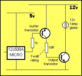
CONNECTING A PIEZO DIAPHRAGM
A piezo diaphragm is essentially very similar to a capacitor (approx22n) as far as the micro is concerned. It requires very little current to operate the device.
A piezo diaphragm is a passive device. It does not contain any active components to create the tone.
Piezo buzzers, piezo sounders and piezo sirens have active components inside the housing (transistors, choke, etc) to create a very loud sound. These devices operate from a DC supply (6v to 12v).
A piezo diaphragm requires a sine wave or square wave – in other words a “pulsing” waveform to cause the diaphragm to “dish” (bend) and thus produce the characteristic annoying sound. The amplitude of the waveform determines the loudness of the sound and the frequency of the waveform determines the tone.
See “10 Tricks for the ‘508A” for more details on driving a piezo.
For more detail: A discussion on the drive-current for the outputs of a PIC12C508A microcontroller