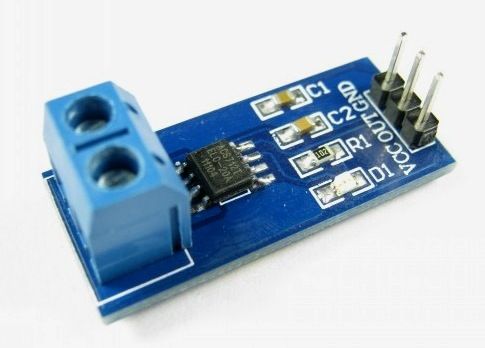
Sensing and controlling current flow is a fundamental requirement in a wide variety of applications including, over-current protection circuits, battery chargers, switching mode power supplies, digital watt meters, programmable current sources, etc. One of the simplest techniques of sensing current is to place a small value resistance (also known as Shunt resistor) in between the load and the ground and measure the voltage drop across it, which in fact, is proportional to the current flowing through it. Whereas this technique is easy and straightforward to implement, it may not be very precise because the value of the shunt resistor slightly varies with its temperature, which in fact is not constant because of the Joule heating. Besides, this simple technique does not provide an isolation between the load and current sensing unit, which is desirable in applications involving high voltage loads. Today, we will talk about Allegro ACS712 device which provides an economical and precise way of sensing AC and DC currents based on Hall-effect. This discussion is divided into two parts. The first part will provide a brief overview of the ACS712 sensor and its characteristics. In the second part, a test experiment will be carried out to interface the sensor with a PIC microcontroller to measure a dc current.
Theory
The current sensing technique based on a shunt resistor is described in How to measure dc current with a microcontroller? and implemented in the Multi-functional power supply project. The major disadvantages of this technique are:
- load is lifted from the direct ground connection
- non-linearity in the response due to Joule heating that drifts the resistance value
- lack of electrical isolation between the load and the sensing part
The Allergo ACS712 current sensor is based on the principle of Hall-effect, which was discovered by Dr. Edwin Hall in 1879. According to this principle, when a current carrying conductor is placed into a magnetic filed, a voltage is generated across its edges perpendicular to the directions of both the current and the magnetic field. It is illustrated in the figure shown below. A thin sheet of semiconductor material (called Hall element) is carrying a current (I) and is placed into a magnetic field (B) which is perpendicular to the direction of current flow. Due to the presence of Lorentz force, the distribution of current is no more uniform across the Hall element and therefore a potential difference is created across its edges perpendicular to the directions of both the current and the field. This voltage is known Hall voltage and its typical value is in the order of few microvolts. The Hall voltage is directly proportional to the magnitudes of I and B. So if one of them (I and B) is known, then the observed Hall voltage can be used to estimate the other.
For more detail: A brief overview of Allegro ACS712 current sensor using PIC16F1847 (Part 1)

