
Summary of Infrared (IR) Object Detection Module Circuit Using IR LED and Photodiode
The article describes a simple, low-cost IR object detection module using an IR LED and photodiode, with an LM358 op-amp, resistors, and a potentiometer. The IR LED transmits infrared light; when an object reflects the IR back, the photodiode senses it and the circuit outputs a signal (middle pin) and lights an indicator LED. The range is adjustable via the potentiometer, and the module can interface with microcontrollers or drive other devices.
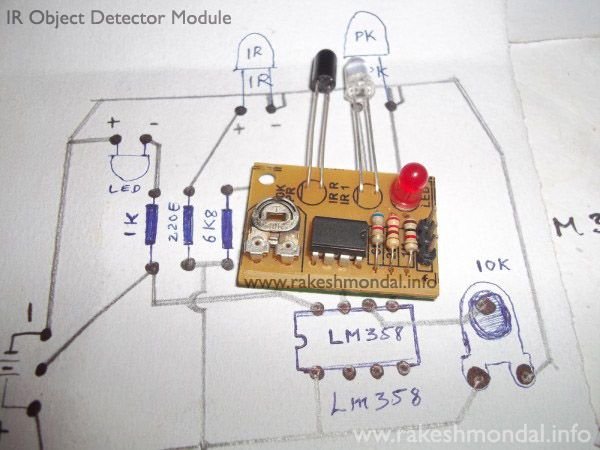
Parts used in the IR Object Detection Module:
- IR LED TSFF5210
- Photodiode BPV10NF
- 1k resistor
- 220Ω resistor
- 6.8k resistor
- 10k potentiometer
- IC LM358
- Indicator LED (regular LED)
How to make Infrared (IR) sensor Object Detection Module Circuit Using IR LED and Photodiode

The IR Object Detection sensor module is quiet easy to make. This sensor circuit below is a low cost – low range infrared object detection module that you can easily make at home using IR LED’s.
We will use a photodiode and IR LED to make a simple circuit. IR led looks like a regular LED that you usually see in Television Remote controls.For now I have added a regular LED to glow as in indicator when something is detected, you can replace it with a buzzer or something else the way you wish.
The Main concept is simple, the IR led keeps transmitting IR infrared rays up to some range (there is a potentiometer also in the design with the help of which you can alter the range). When some object comes in the (IR) infrared range, the IR waves hits the object and comes back at some angle, The Photo diode next to IR led detects that IR infrared rays which got reflected from the object and hence works as a proximity sensor. You can read more details about Proximity sensors for more.

The components required to make this IR sensor can be easily found in any electronic stores and it is quiet inexpensive.
IR Sensor Circuit Module Requirements
1 – IR LED TSFF5210
1 – PR (photodiode) BPV10NF
1 – 1k resistance
1 – 220E resistance
1 – 6k8 resistance
1 – 10k potentiometer
1 – IC LM358
Infrared sensor Module Schematics
Following this schematic you can easily make it on a breadboard, I intentionally drew this schematic for this IR sensor this way so that it can easily printed on the copper board in no time if you have some etching solution.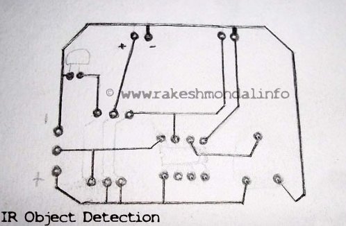

For now in this circuit an LED would glow as an example. Notice that there are three pins in the schematic in which two pins are used to provide power to the infrared sensor and the Middle pin is unused, and can be used for other operation. The Middle pin goes high (Logic 1) if the photodiode in this object detection module detects an object, and hence can be interfaced with other devices. You can use it the way you wish, it can be used to run some DC motors and make a simple robot. The middle pin of the IR Sensor Circuit can be interfaced with Microcontroller easily to do complex operations,or you can interface an LCD with microcontroller and have the status of the sensor displayed on the LCD very easily as in my next tutorial for interfacing multiple IR Sensors with Arduino and LCD.
Source : Infrared (IR) Object Detection Module Circuit Using IR LED and Photodiode
- How does the IR object detection module detect objects?
The IR LED transmits infrared rays which reflect off objects; the photodiode detects the reflected IR and the circuit signals detection. - What components are required to build the IR sensor circuit?
The circuit uses an IR LED TSFF5210, photodiode BPV10NF, 1k, 220Ω, 6.8k resistors, 10k potentiometer, LM358 IC, and an indicator LED. - Can the detection range be adjusted?
Yes, a 10k potentiometer is included to alter the detection range. - What does the middle pin on the module do?
The middle pin goes high (logic 1) when the photodiode detects an object and can be used for other operations or interfacing. - Can this module be interfaced with a microcontroller?
Yes, the middle output pin can be interfaced with a microcontroller for more complex operations. - Is the indicator LED required?
No, the indicator LED is used as an example and can be replaced with a buzzer or other output as desired. - Can the module drive motors or other devices directly?
The article suggests the middle pin can be used to run DC motors or similar, implying direct or interfaced control as needed. - Is the circuit suitable for breadboard and PCB etching?
Yes, the schematic is drawn for easy assembly on a breadboard and for printing on copper board for etching.
