Summary of RS232 Communication with PIC Microcontroller
This article explains how to establish simple RS232 serial communication between a PIC microcontroller and a PC (or another microcontroller), including required hardware, software examples (CCS C), wiring, and PC terminal setup. It covers level shifting with MAX232, PIC clock considerations for baudrate, CCS C UART directives and I/O functions, and using a terminal (HyperTerminal) to send/receive data.
Parts used in the RS232 communication with PIC Microcontroller:
- PIC microcontroller (example PIC18F2620)
- MAX232 or compatible RS232 level converter chip
- 4 external capacitors for MAX232 charge pump
- DB9 female connector
- RS232 cable (DB9)
- USB to serial converter (if PC lacks serial port)
- PIC development/experiment board (optional)
- Programmer to flash HEX file (e.g., PICPgm Programmer)
Description
This article shows how to do a simple communication via a RS232 interface with a PIC microcontroller. RS232 is a standard for a serial communication interface which allows to send and receive data via at least three wires. With the RS232 interface it is possible to setup a connection between a microcontroller and a PC (via PC’s COM port) or between two microcontrollers.
The RS232 interface can be used for many purposes like sending commands from a PC to a microcontroller, send debug information from a micontroller to a terminal, download new firmware to the microcontroller and many other things.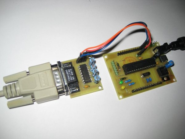
In this tutorial I will show how to link a PIC microcontroller to a standard PC. On the PC we will use a termial program to send and receive data. Data sent by the microcontroller will be shown in the terminal window and any key pressed inside the terminal will send the corresponding key code to the microcontroller. We will use this simple configuration to test and understand the RS232 communication.
Note that modern PCs don’t have a serial port so you need to get a USB to serial converter. They are available at low cost.
Block Diagram
The following block diagram shows the whole setup:
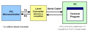
For serial communication the line used to transmit data is called TX and the line used to receive data is called RX. The level converter is required to translate the voltage level of the microntroller to RS232 voltage level. The microntroller operates at TTL level (0V = logic 0, +5V logic 1) whereas RS232 uses around +/-12V. A very famous RS232 level converter is the MAX232 chip.
Hardware
In the schematic below a PIC microcontroller is connected to the RS232 level converter chip. A PIC18F2620 micocontroller is used, but it will also work with any other microcontroller which has a built-in UART.
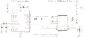
The PIC is running at 10MHz. This will be important later when we configure the baudrate for the serial communication.
Ther RS232 level converter uses the famous MAX232 chip, but any other MAX232 compatible chip will also work. It just requires 4 capacitors to do its job. These external capacitors are required for the charge pump inside the chip which generates the required voltage levels.
The connections on the DB9 connector between pins 1,4,6 and 7,8 are required to satisfy the RS232 hardware handshake signals which we will not use here.
I have developed a RS232 module which allows direct connection to the microcontroller. It consists of a DB9 Female connector, a MAX232 compatible RS232 level converter and the capacitors. You can find the RS232 module here.
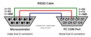
RS232 Cable
To connect the above circuit to the PC we need a RS232 cable. The below picture shows the necessary connections.
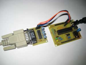
Hardware Picture
Below a picture of the hardware setup. As you can see I have used my PIC16F/18F Experiment Board and my RS232 Module.
Software
Now since the hardware is ready we have to write the software for the PIC microcontroller. The different compiler vendors provide different ways to setup the UART in the PIC. So I will show how to use the UART for different compilers.
RS232 communication with CCS C compiler
The CCS C compiler provides a very simple way to do serial communication via RS232. It hides all the register settings for the user. Only the some parameters have to be provided, the rest is done by the compiler. By the way, the CCS C compiler also allows to do RS232 communication via general I/O pins, i.e. software based RS232 communication instead of using the built-in UART. That is a really great feature of the CCS C compiler.
Here the code lines which are required to setup the UART for RS232 communication.
#use delay(clock=40000000)
#use rs232(baud=57600,parity=N,xmit=PIN_C6,rcv=PIN_C7,bits=8)
As you can see, it is very simple!
The #use delay directive provides the compiler with the information about the clock frequency at which the PIC is running. We run the PIC at 10MHz with the 4X PLL fuse enabled, hence it is running at 40MHz, so we have to set clock=40000000.
The #use rs232 directive provides the compiler the information about the RS232 parameters which shall be used for the communication. It is more or less self explaining:
- baud=57600: specifies the baud rate for communication, we will use 57600 baud
- parity=: specifies whether a parity bit shall be used or not, we will not use it, hence we disable it
- xmit=PIN_C6: specifies the pin to be used for transmission, since we want to use the built-in UART we have to use pin RC6
- rcv=PIN_C7: specifies the pin to be used for receiption, since we want to use the built-in UART we have to use pin RC7
- bits=8: specifies the number of bits per transmitted data
To transmit data the following functions can be used:
int value = 1;
putc('A');                              /* transmit a character via RS232 */
puts("Test-String");                    /* transmit a string via RS232 */
printf("Transmit a value: %d", value);  /* send formatted string via RS232 */
To receive data the following functions can be used:
char ch;
char string[32];
ch = getc();                        /* receives a single character via RS232 */
gets(string);                       /* receives a string via RS232, reads */
/* characters into the string until RETURN */
/* character (13) is encountered */
Here a simple demo program for the CCS C compiler. Project download link. To run the demo, the HEX file needs to be flashed into the PIC, e.g. with PICPgm Programmer.
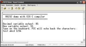
/*****************************************************************************/
/* RS232 communication demo wiht CCS C compiler                              */
/*****************************************************************************/
#include <18F2620.h>
#device adc=16
#FUSES NOWDT                     //No Watch Dog Timer

#FUSES WDT128                    //Watch Dog Timer uses 1:128 Postscale

#FUSES H4                        //High speed osc with HW enabled 4X PLL

#FUSES NOBROWNOUT                //No brownout reset

#FUSES LVP                       //Low voltage prgming

#FUSES NOXINST                   //Extended mode disabled (Legacy mode)

#use delay(clock=40000000)
#use rs232(baud=57600,parity=N,xmit=PIN_C6,rcv=PIN_C7,bits=8)
void main()
{
int value = 85;
char ch;
char string[64];
puts("**********************************");
puts("  RS232 demo with CCS C compiler  ");
puts("**********************************");
/* start a new line (CR + LF) */
putc('\n');
putc('\r');
/* output variable in decimal format */
printf("Decimal variable output: %d\n\r", value);
/* output variable in hex format */
printf("Hex variable output: %x\n\r", value);
/* echo demo: PIC receives data and sends it back. */
/*            If ENTER key is received, this demo exits. */
puts("Type on the keyboard, PIC will echo back the characters:");
while (1)
{
/* read a single character */
ch = getc();
/* echo back the received character */
putc(ch);
}
}
RS232 communication with HI-TECH C compiler
To be done …
PC connection
Now, since we have the required hardware and firmware, we can connect the hardware to the PC.
To be able to see the data transmitted from the Microcontroller and to send data to the Microcontroller we have to run a terminal program on the PC. There are a lot of terminal programs available. I will show here how to use HyperTerminal which is included in Microsoft Windows.
HyperTerminal Setup
If you are using Windows XP start HyperTerminal. You can find it in the Communication Folder: Start Menu->All Programs->Accessories->Communication.
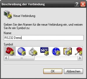
On startup it will ask for a connection name. Just enter a text which will identify the connection, e.g. use “RS232 Demo”. In the next dialog select the COM port where the PIC is connected to.
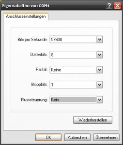
In the following dialog we have to set the connection properties. Needless to say, the properties have to match the settings we are using in the PIC.
Once this is done, just reset the PIC and the demo output shal be visible.
For more detail: RS232 Communication with PIC Microcontroller
- What is required to convert PIC TTL levels to RS232 levels?
The MAX232 or any MAX232 compatible level converter chip and four external capacitors are required to translate TTL to RS232 voltages. - Can I connect the PIC directly to a PC COM port?
No, you must use a level converter like MAX232 between the PIC TTL pins and the PC COM port. - What PIC pins are used for hardware UART transmission and reception in the example?
Pin RC6 is used for transmit (TX) and pin RC7 is used for receive (RX). - What clock setting is used in the CCS C example and why?
The PIC runs at 10MHz with the 4X PLL enabled, so the compiler is given clock=40000000 to reflect 40MHz operation. - What baud rate and frame format does the CCS C example use?
The CCS C example uses 57600 baud, no parity, 8 data bits. - Which CCS C directives configure the UART and clock?
#use delay(clock=40000000) configures the clock and #use rs232(baud=57600,parity=N,xmit=PIN_C6,rcv=PIN_C7,bits=8) configures the UART. - How can I send and receive characters in CCS C?
Use putc to transmit a character, puts or printf to send strings, getc to receive a single character, and gets to receive a string until RETURN. - Do I need to handle RS232 hardware handshake signals for this demo?
No, the demo connects certain DB9 pins (1,4,6 and 7,8) to satisfy handshake lines but does not use hardware handshake in practice. - What terminal program is demonstrated for PC connection?
HyperTerminal on Windows is demonstrated to view transmitted data and send keystrokes to the PIC.