PicKit2 is a programmer designed by Microchip to program its pic microcontrollers. PicKit2 supports many 8-bit pic microcontroller series. PicKit2 supports almost all Pic-10/12/16/18/24 and dspic-30/33 flash series microcontroller’s. Pickit 2 is an ICSP (In-circuit serial programmer) programmer. In icsp interface, microcontroller can be programmed while its working in the circuit. An icsp programmer uses 5 pins to program the target microcontroller. Pickit 2 uses an on board pic18f2550 microcontroller that programs the target microcontroller. Pic18f2550 communicates with the computer software using its usb interface and talks with the target microcontroller using its icsp interface. Thanks to microchip that they released the pic18f2550 program software. Now one can reverse the pickit 2 circuit can make pickit 2 programmer at home as a diy project.
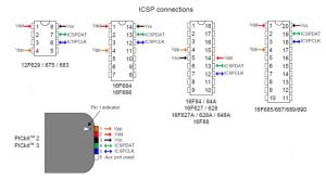
Pickit 2 requires the following pic microcontroller pins to program it.
- PGC (Clock input to microcontroller)
- PGD (Data Input to microcontroller)
- Vpp (Programming Mode voltage)
- Vdd (Power Pin Apply 5v to it)
- Gnd (Ground this Pin)
To program a pic microcontroller one have to Identify the upper 5 pins on his pic microcontroller and then make connections with the pickit 2 icsp header. See the datasheet of your pic microcontroller to Identify these pins and then connect the signals from PicKit2 to these pins. Normally all the pic microcontrollers have icsp pins located on the pin numbers given below.
I designed a copy of PicKit 2 programmer clone at home as a diy project. All the components required to build the kit can easily be found on an electronics store. I bought all the components from an online electronics store.
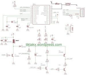
The circuit which I followed to build the Kit is obtained from
http://tiktakx.wordpress.com/2011/04/14/yet-another-simplified-pickit2-clone/
I made some changes in the Circuit.
- Inductor which i used in my Pickit2 is 680uH.
- Push Button with Pin#26 is included to reload the boot loader if in case boot loader is corrupted.
If you use the circuit given at tiktakx.wordpress.com you will be unable to load the boot loader, if in case it is corrupted. You than have to manually remove the Pic18F2550-ICSP controller from Kit and reprogram it from another Pickit2. Circuit diagram of the clone is given below.
My final kit is below. I made Pickit2 and program executor on a single board. I program Pic microcontroller on one side, then remove the controller, put it on other side of zif socket, apply power and my program starts executing.
Note: My PicKit2 is picked by my PC on first time, when I first attached it to PC. It means there is no problem in Circuit and components. I didn’t receive any error in PicKit2 hardware or Software part. Means I am Lucky:D
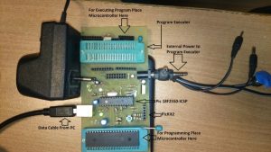
I divided my board in two parts.
- Program Executer
- PicKit2 circuit
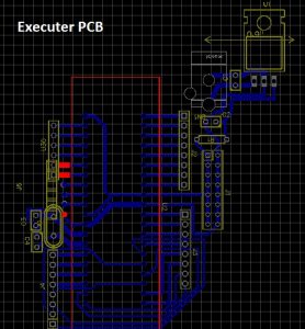
I made the PCB for both circuit’s program executer and PicKit2. Then I printed them on PCB Sheet one by one manually. First printed the Circuit on Sticker sheet using a laser printer, then stickered the circuit on PCB Sheet with the help on an iron.
I designed the PCB of both the Program executer and PicKit2 circuit using online PCB editor software EasyEda. Easyeda is online PCB editor software and it’s easy to use and design PCB using easy eda. Numerous Per-Defined components footprints are available in Easyeda, you can also import and use footprints of many other PCB editor software’s in easy eda.
Download the pickit 2 programmer Pcb files from the links below
PicKit2 pic18f2550 programming file – Boot loader
Just connect your PicKit2 to your PC. Open MPLAB-IDE Go to Programmer>Select Programmer>PicKit2. As soon as you select PicKit2 a status will appear on MPLAB window which says <span “font-family:”georgia”,”serif”;mso-bidi-font-family:calibri;mso-bidi-theme-font:=”” minor-latin”=””>Pickit2 Found and you will see MPLAB loading boot Loader in PicKit2.