
Summary of DS18S20 interfacing with pic and avr microcontroller
This article details a project to read temperature data from a DS1820 sensor using a PIC16F/18F Development Board. The system utilizes the microcontroller's ADC pin to capture sensor readings, which are then transmitted to a PC via UART for display in Hyper Terminal. The guide covers hardware interfacing, pin assignments, C programming logic, compilation steps using MPLab and Hi-Tech Compiler, and testing procedures involving power supply and serial connections.
Parts used in the PIC16F/18F Primer Board Project:
- PIC16F/18F Development Board
- DS1820 Temperature Sensor
- USB Port (for ISP)
- Serail Cable
- PC with Hyper Terminal
- MPLab Software
- Hi-Tech Compiler
- PICKIT2 Software
Microcontroller BoardsRead the temperature in PIC16F/18F Primer Board from temperature sensor ds1820. The PIC16F/18F Primer board uses the ADC pin for reading temperature from temperature sensor ds1820. The reading output is displayed into PC through UART.
PIC16F/18F Development Board
The PIC16F/18F Development Board is specifically designed to help students to master the required skills in the area of embedded systems. The kit is designed in such way that all the possible features of the microcontroller will be easily used by the students. The kit supports in system programming (ISP) which is done through USB port.
Microchip’s PIC (PIC16F877A), PIC16F/18F Development Kit is proposed to smooth the progress of developing and debugging of various designs encompassing of High speed 8-bit Microcontrollers.
Temperature Sensor
DS1820 is a temperature sensor which is small sensor. The output of sensor converted to digital that easy connecting with microcontroller.
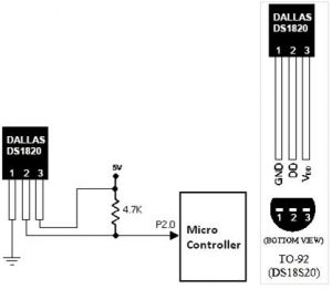
Interfacing ds1820
Fig. 1 shows how to interface the ds1820 to microcontroller. As you can see the first pin is connected to GND, the third pin is connected to VCC & the second pin is connected to the Microcontroller. So when the temperature is sensing, it give the sensor reading to controller.
Interfacing ds1820 with PIC16F877A
We now want to read the temperature in PIC16F/18F Development Board from temperature sensor ds1820. The PIC16F/18F Development Board uses the ADC pin for reading temperature from temperature sensor ds1820. The reading output is displayed into PC through UART.
The 10 bit ADC used to read temperature. Basic clocking for the A/D converters is provided by the VPB clock. A programmable divider is included in each converter, to scale this clock to the 4.5 MHz (max) clock needed by the successive approximation process. A fully accurate conversion requires 11 of these clocks.
Pin Assignment with PIC16F877A
Circuit Diagram to Interface ds1820 with PIC16F877A
Source Code
The Interfacing ds1820 with PIC16F877A program is very simple and straight forward, that reading temperature from temperature sensor ds1820 and it display into PC through serial port.
C Program to read temperature using PIC16F877A
*****************************************************************************************
Title : Program to read temperature
*****************************************************************************************
#include

#include

#include "delay.c"

__CONFIG(0x3f72);

#define DQ RC0

#define DQ_DIR TRISC0

#define FOSC 10000 #define BAUD_RATE 9.6

// 9600 Baudrate

#define BAUD_VAL (char)(FOSC/ (16 * BAUD_RATE )) - 1;

// Calculation For 9600 Baudrate @10Mhz unsigned char i=0;

float Temerature=0; void ds1820_init();

void Reset(void);

void write(unsigned char);

unsigned char Read(void);

void Serial_init();

void main()

{

unsigned char Temp[9];

DelayMs(100);

Serial_init();

ds1820_init();

DelayMs(100);

printf("\033[2J");

// Clear the Hyper terminal;

while(1)

{

Reset();

write(0xcc);

write(0x44);

DQ_DIR = 1;

DelayUs(10);

while(!DQ);

// this will be raised after finishing conversion Reset();

write(0xcc);

write(0xbe);

for(i=0;i<9;i++)

Temp[i] = Read();

// Read 9 bytes for(i=0;i<9;i++) printf("%d ",Temp[i]);

printf("Temperature:%3.1f%cC",(float)Temp[0]/2,0xf8); printf("\r");

DelayMs(250);

DelayMs(250);

DelayMs(250);

DelayMs(250);

}

}

void ds1820_init()

{

DQ = 1;

DQ_DIR = 1;

// pull up

}

void Reset(void)

{

DQ_DIR = 0;

DQ = 0;

DelayMs(1);

DelayUs(250);

// 500us DQ_DIR = 1;

DelayUs(100);

// 40us while(DQ==1);

// wait until presence pulse DelayMs(1);

DelayUs(250);

// 500us

}

void write(unsigned char cmd)

{

for(i=0;i<8;i++)

{

DQ_DIR = 0;

// pull down DQ = 0;

DelayUs(25);

// 10us DQ = (cmd & 0x01)?1:0;

// Send bit cmd = cmd >> 1;

DelayUs(120);

// >45us DQ_DIR = 1;

// release

}

}

unsigned char Read(void)

{

unsigned char temp=0,RecDat=0;

for(i=0;i<8;i++)

{

DQ_DIR = 0;

DQ = 0;

// pull down DelayUs(25);

// 10us DQ_DIR = 1;

// release DelayUs(25);

// 10us temp = DQ;

// read bit temp = temp<<i;

RecDat |= temp;

DelayUs(70);

// 30us

}

return RecDat;

}

void Serial_init()

{

TRISC=0xc0;

// RC7,RC6 set to usart mode(INPUT) TXSTA=0x24;

// Transmit Enable SPBRG=BAUD_VAL;

// 9600 baud at 10Mhz RCSTA=0x90;

// USART Enable, Continuous receive enable TXIF=1;

// Start Transmit } void putch(unsigned char Data)

// data TX required for printf

{

while(TXIF==0);

TXREG = Data;

}
To compile the above C code you need the Mplab software & Hi-Tech Compiler. They must be properly set up and a project with correct settings must be created in order to compile the code. To compile the above code, the C file must be added to the project.
In Mplab, you want to develop or debug the project without any hardware setup. You must compile the code for generating HEX file. In debugging Mode, you want to check the port output without Development Board.
The PICKIT2 software is used to download the hex file into your PIC16F/18F Development Board through USB port line.
Testing the ds1820 with PIC16F877A
Give +12V power supply to PIC16F/18F Development Board; the serial cable is connected between the controller and PC. Open the Hyper Terminal screen, select which port you are using and set the default settings. Now the screen should show the current temperature readings.
Bring a Hot soldering iron tip near the ds1820‘s pins, don’t touch it keep it 1 or 2mm away. The screen should update with the rising temperature. Now finally touch the pins of ds1820 with the tip of iron, the temperature should rise quickly. Keep it there until temperature rise to 80 degrees, and then remove the iron.
If any data is not coming in Hyper Terminal, then you just check the serial cable is working or not. Otherwise you just check the code with debugging mode in Mplab. If you want to see more details just see the videos in below link.
Source: DS18S20 interfacing with pic and avr microcontroller
- How is the temperature reading displayed on the PC?
The reading output is displayed into the PC through UART. - What is the purpose of the USB port on the development board?
The kit supports in system programming (ISP) which is done through the USB port. - Which pins of the ds1820 are connected to GND and VCC?
The first pin is connected to GND and the third pin is connected to VCC. - What type of ADC is used to read the temperature?
A 10 bit ADC is used to read the temperature. - What software is required to compile the C code?
You need the Mplab software and Hi-Tech Compiler to compile the code. - How do you download the hex file into the development board?
The PICKIT2 software is used to download the hex file into your PIC16F/18F Development Board through the USB port line. - What happens if no data appears in Hyper Terminal?
You should check if the serial cable is working or check the code with debugging mode in Mplab. - How can you test if the temperature sensor is rising correctly?
Bring a hot soldering iron tip near the ds1820's pins without touching them to see the screen update with rising temperature.
