Summary of A Versatile PIC16F876A Based Robot
This article describes a miniature robotic vehicle designed to conquer various terrains using a dual-track system powered by two DC motors. The robot features a four-bar linkage on each side, allowing independent track elevation via servos for multiple configurations. Controlled by a PIC16F876A microcontroller, it utilizes an LCD, keypad, and sensors (IR proximity and accelerometer) to navigate obstacles and adjust stability automatically across three distinct modes.
Parts used in the Miniature Robotic Vehicle:
- Two DC motors
- Quadruple half H-Driver
- Four bar linkage (two units)
- Servos (two servo motors)
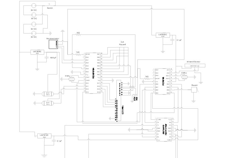
- PIC16F876A microcontroller
- LCD display
- Keypad
- Proximity sensor (IR sensor)
- Accelerometer
- Buzzer
- Potentiometer
- Simple switch
Design Summary:
Our group designed and manufactured a miniature robotic vehicle that conquers various terrains. The vehicle was designed with a track system which is powered by two DC motors. The motors use a Quadruple half H ‐Driver in order to drive the motors in both directions. The track system incorporates a four bar linkage for each tread. These two linkages allow each side to be independently raised which gives the robot multiple configurations. These configurations
allow the vehicle to drive on various terrains.
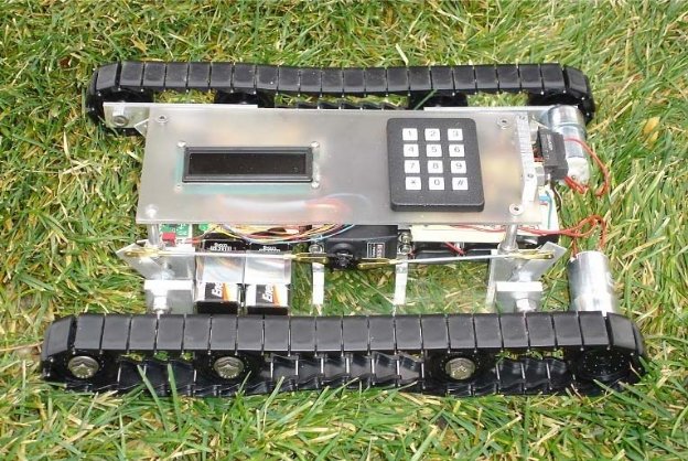
The robot is initially turned on with a simple switch. The LCD displays multiple mode options and gives directions for selecting a mode. Once the user selects the mode via the keypad they are then asked whether they want full speed, half speed, or stationary. Once selected the robot carries out the chosen mode and speed. While running, the LCD displays what current action the robot is carrying out.
During mode 1 the vehicle tracks remain flat and the proximity sensor becomes the main input. Once the sensor passes a certain threshold the robot reverses, turns, resumes forward motion at half speed via PWM for one second, and then continues on at full speed. Mode 2 will be the same as mode 1, but the tracks remain in the raised position. For mode 3 the tracks default position is raised but the accelerometer becomes another source of input. The accelerometer
data is used to tell the robot’s position relative to gravity. If the robot is climbing steep terrain the y output from the accelerometer will pass a determined threshold. Once this occurs the robot will reconfigure to flat configuration for lower center of gravity and maximum traction. If
the robot is traversing along a slanted incline or object the x output from the accelerometer will pass a set threshold. Once this occurs one side will reconfigure to flat dependent on which side
is tilted.
Design Evaluation:
The robot and all of its elements worked very well. Our output displays worked the way we needed them to. We have a simple LED that lights up when the robot power is on and the LCD displays our mode and speed menus exactly how we wanted it to. For our audio output device we used a buzzer. There is a very short buzz about once a second while the ro bot backs up. This is
one element that we could have chosen to use something more difficult, but there were other elements that were far more crucial to the functio nality of the robot that we chose to spend the extra time on.
Our three manual data inputs are a potentiometer, switch, and keypad, all of which work well. The switch turns the robot on and off, the potentiometer is used to control the contrast of the LCD, and the keypad is used to select the track configuration mode and motor speed. We also used two automatic sensor inputs which were an accelerometer and an IR sensor. The accelerometer works great. When the robot is tilted past a certain point the servos will change the track configuration depending on wh ich way the robot is tilted and then set them back to normal position once level again. The IR sensor works great, too. We used it to tell the robot when it is about one foot away from a wall or tall obstacle, at which time it stops, backs up for about a foot, turns right for 1.5 seconds or about 60-70 degree s, then proceeds to drive forward again.
The actuators we used were two servo motors and two PWM speed controlled and reversible DC motors. The servos control the linkage for the tracks and puts them at either 45 degrees or flat which is exactly what we wanted them to do. The two motors are for the robots drive train. We were able to get them to reverse and change speed just as we wanted. They also turn separate
directions simultaneously, which we used to turn the robot.
For more detail: A Versatile PIC16F876A Based Robot
- How does the robot detect obstacles?
The robot uses an IR sensor to detect when it is about one foot away from a wall or tall obstacle. - What happens when the robot detects an obstacle?
It stops, backs up for about a foot, turns right for 1.5 seconds, and then drives forward again. - How does the robot determine its position relative to gravity?
The accelerometer data tells the robot's position relative to gravity based on x and y outputs. - When does the robot reconfigure to a flat configuration?
The robot reconfigures to flat if climbing steep terrain or traversing a slanted incline where thresholds are passed. - What components control the track linkages?
Two servo motors control the linkage for the tracks, setting them at either 45 degrees or flat. - How are the DC motors driven in both directions?
A Quadruple half H-Driver is used to drive the motors in both directions. - What manual inputs does the robot use?
The robot uses a potentiometer, a switch, and a keypad as manual data inputs. - What audio feedback does the robot provide?
A buzzer produces a very short buzz about once a second while the robot backs up.