
Summary of A simple 50 MHz diy microwattmeter using PIC16C84
This article describes a DIY microwattmeter design operating from 2 to 50 MHz with an input range of -75 dBm to +5 dBm. The system utilizes an AD606 log-converter for signal level measurement and frequency counting via its limiter output. A PIC16C84 microcontroller manages the ADC (MAX186) readings, calculates dBm values using frequency-dependent factors, and drives an HD44780 LCD display. The project includes a self-built programmer and detailed assembler code for frequency resolution of 1 kHz and level resolution of 0.1 dBm.
Parts used in the Simple Microwattmeter:
- AD606 log-converter
- MAX186 ADC
- PIC16C84 microcontroller
- HD44780 type LCD
- David Tait's low-cost parallel port programmer
Summary.
A design for a simple microwattmeter. Input range -75 dBm to + 5 dBm. Frequency range 2 to 50 MHz. Level resolution is 0.1 dBm, frequency resolution is 10 kHz. Log-output about 0.5 – 3.5 Volt. Output for external counter. The meter uses a AD606 as log-converter, a MAX186 as ADC, a PIC16C84 as controller and a HD44780 type LCD. The PIC measures frequency and level of the input signal and calculates level in dBm using frequency-dependant factors. Details of the design are provided as well as a listing of the PIC assembler program.
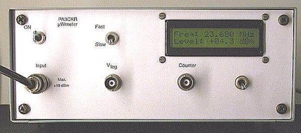
In January 1997 I saw the datasheet of the Analog Devices AD606, a chip that will convert a -75 dBm to +5 dBm RF input level to a corresponding DC output between 0.5 and 3.5 Volts. The chip will work up to 50 MHz. It also has a limiter output for frequency measurement purposes. I tried the AD606 using a basic application circuit as recommended in the datasheet.
At the same time I saw designs appearing which used a Microchip PIC16C84 microcontroller. It seemed that this chip was well suited to the needs of the hobbiest: simple architecture, cheap, 1024 words of eeprom program memory and easy to program and reprogram using a programmer you can build yourself.
First, I subscribed to the PICLIST This list proved to be an invaluable tool to quickly learn about most aspects of PIC microcontrollers. I first built the programmer, using the design of David Tait . David has a schematic and software for a low-cost programmer to connect to a PC parallel port. I then used his example of a first circuit to build, a simple LED-flasher.
Next, I acquired some used LCD character displays using a Hitachi HD44780 controller. How to use these things ? Again, David Tait had a simple C program to test LCD displays connected to a PC parallel port. I also read the excellent LCD overview by by Peer Ouwehand .
I then downloaded the necessary assembler (MPASM) from Microchip and used Peer’s examples to test a PIC16C84 and a display. This worked well so I began thinking of constructing a serious application: a PIC controlled microwattmeter. This instrument would use the AD606, and the PIC would control an ADC to measure the AD606 output voltage and also count the AD606 limiter pulses to give an indication of the signal frequency.
First I concentrated on measuring frequency. Numerous examples to do this with a PIC are available, I used an example provided by Simone Benvenuti and Andrea Geniola , I don’t remember from which site I picked up the example. In this design frequency is measured by counting pulses on RA4 during one millisecond.
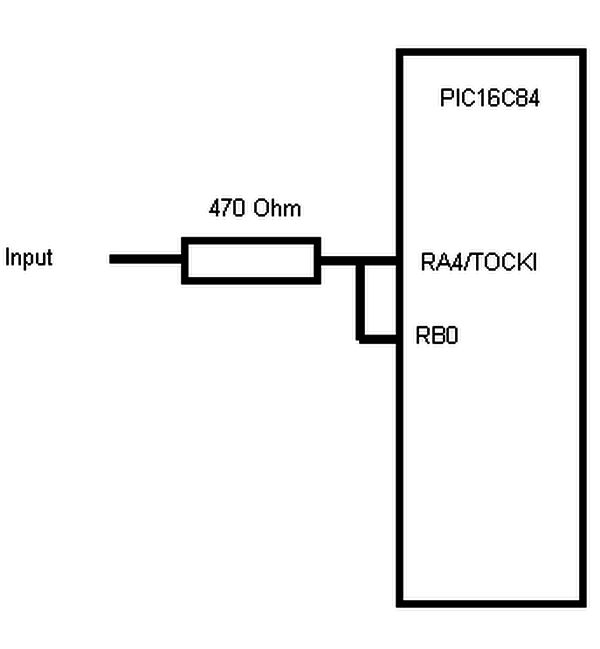
This time is determined by a delay loop. The counter is activated during this time by three-stating another pin (in this example RB0) connected to the counter pin. The counter is stopped by pulling this pin low. The measured frequency thus has a resolution of 1 kHz.
For more detail: A simple 50 MHz microwattmeter using PIC16C84
- What is the input range of the designed microwattmeter?
The input range is from -75 dBm to +5 dBm. - How does the AD606 chip function in this circuit?
The AD606 converts RF input levels between -75 dBm and +5 dBm into a DC output voltage ranging from 0.5 to 3.5 Volts. - What determines the frequency resolution of the device?
The frequency resolution is determined by counting pulses on RA4 during a one-millisecond delay loop, resulting in a 1 kHz resolution. - Can the PIC16C84 be programmed without expensive equipment?
Yes, the article mentions building a low-cost programmer connected to a PC parallel port using designs by David Tait. - Does the meter account for frequency variations when calculating power?
Yes, the PIC calculates the level in dBm using frequency-dependent factors. - What is the purpose of the limiter output on the AD606?
The limiter output is used for frequency measurement purposes by providing pulses that the PIC counts. - How is the frequency measured within the millisecond time frame?
The counter is activated by three-stating pin RB0 connected to the counter pin and stopped by pulling it low. - What software was used to develop the PIC controller program?
The MPASM assembler downloaded from Microchip was used to write the PIC assembler program.
