
Summary of Bicycle Persistence of Vision Light Display — February 2007
In February 2007, the author prototyped a bicycle wheel display using LEDs controlled by an ATTiny861 microcontroller. The design features 48 LEDs managed via 74x373 ICs for high-speed updates and full-resolution bitmap storage, eliminating external resistors to save space. Additionally, the text references a retrofitted HERO-1 robot using an ATMega8535 processor and a 2001 multi-channel light dimmer project utilizing a PIC 16F84 chip.
Parts used in the Bicycle Persistence of Vision Light Display:
- ATTiny861 microcontroller
- 48 LEDs (24 on each side)
- 74x373 ICs
- Two fully charged AA or AAA batteries
- PCB board
- 8-bit bus
In February of 2007 I spent a little while prototyping a board that turns any bicycle wheel into a moving display billboard using a single string of LEDs. The idea was to do something that would be very visible, turn itself on and off automatically, have enough processing power to dynamically generate bike computer style displays, and have enough memory to store full resolution bitmaps.
The first revision was a hand built board using a single ATTiny26 micro, 14 LEDs, a resistor array, and a magnetic reed switch.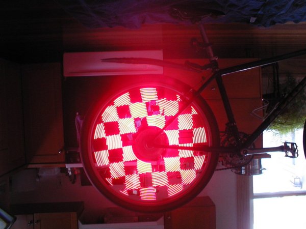
Next I drew up a board using PCB and had it printed. The printed board differed in a couple of ways from the original hand-built prototype:
- More LEDs: 48 LEDs total, 24 on each side of the board. This gives higher resolution patterns, and they can be seen from both sides of the bike. The LEDs are controlled from a series of 74×373 ICs connected to an 8 bit bus on the microcontroller. As opposed to shift registers, all 48 LEDs can be updated in 20-30 microcontroller cycles, leaving plenty of time to spare to figure out what should go there.
- No Resistors: Turns out the I/V curve of the particular 74x family IC I had maxed out at around 20mA with two fully charged AA or AAA batteries with no series resistor. Yeah!
- Bigger Micro: While the ATTiny26 is very versatile, the ATTiny861 is a strict superset including 8k of program memory. All the better to store full resolution bitmap patterns in.
And some pictures of the final product: (some have been flipped to account for my lack of a proper bicycle stand)
HERO-1 Robot — April 2004
Zia and I have spent a good amount of time retrofitting a HERO-1 to use a little more modern technology. We replaced the processor board with an Atmel ATMega8535, and some of the peripherals are controlled by ATTiny26’s so that they are all capable of operating simultaneously. I don’t have any code yet, but here are a few pictures of the retro-fitted robot.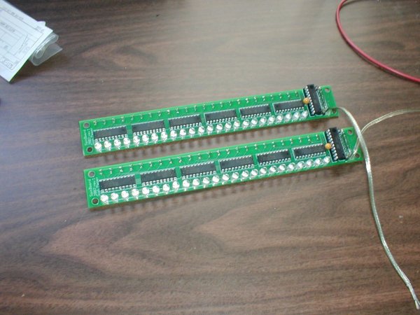
Multi-channel serial bus light dimmer — November 2001
Here is the PIC source for the finished 6 channel light dimmer and 232-485 transceiver. Also have schematics and source code for an xmms plugin to create patterns. Video of the resulting light show.
PIC 16F84 6-Channel Light Dimmer dimmer-010902.tar.gz
PIC 16F84 232-485 half-duplex transceiver 232-485-010902.tar.gz
pic_includes-010902.tar.gz – Necessary includes
PCB Board we used for the dimmer
PCB Board etch pattern
Schematic – the best schematic I have PDF Version
Full source for xmms plugin and all utilities needed to drive the lights anim.2001-110902.tar.gz
For more detail: Bicycle Persistence of Vision Light Display — February 2007
-
What was the primary goal of the 2007 prototype?
The goal was to turn any bicycle wheel into a moving display billboard that is highly visible, operates automatically, and can store full resolution bitmaps. -
How many LEDs are included in the final printed board version?
The final printed board uses 48 LEDs total, with 24 located on each side of the board. -
Which microcontroller replaced the original ATTiny26 in the second revision?
The ATTiny861 microcontroller was used because it is a strict superset including 8k of program memory. -
Why were series resistors removed from the circuit design?
Resistors were removed because the I/V curve of the 74x family IC maxed out at around 20mA with two fully charged AA or AAA batteries without them. -
How fast can all 48 LEDs be updated compared to shift registers?
All 48 LEDs can be updated in 20-30 microcontroller cycles, which is faster than using shift registers. -
What components control the LEDs in the new PCB design?
A series of 74x373 ICs connected to an 8 bit bus on the microcontroller controls the LEDs.
