Summary of 8 Channel PWM Power MOSFET LED Chaser for PIC16F628A
This article describes an 8-channel LED chaser circuit using a PIC16F628A microcontroller. It features 5-bit PWM for four intensity levels, three run modes (sequential, random, manual), and non-volatile memory for settings. The design includes on-board monitoring LEDs, power MOSFETs for driving high-current loads up to 2 amps per channel, and a 7805 voltage regulator. It supports mixed LED colors and sizes, making it suitable for toys and models.
Parts used in the 8 Channel PWM Power MOSFET LED Chaser:
- PIC 16F628A microcontroller
- Eight STP36NF06 N-Channel MOSFETs
- 7805 3-terminal 5 volt regulator
- Resistors R1 through R8
- Resistor R25
- Resistor R26
- Capacitor C1
- Capacitors C2 and C4
- Diode D1
- Diode D14
- 120R gate resistors
- 47K gate pull-down resistors
- Switch S1
- 3-way terminal block
- ICSP header
Description
Update: Variable chase speed option kit now available (see here for details)
This neat little circuit provides 8 LEDs directly driven from the PIC along with a single mode control switch. The firmware elsewhere on this page drives the LEDs with a 5 bit PWM signal providing each of the 8 LED channels with four levels of intensity; off, dim, mid, bright. A number of sequences are programmed into the firmware to provide some interesting visual effects and chase sequences, including the classic effect seen on the car in the Knight Rider TV series.
The software has sequential, random and manual sequence run modes and manual advance to the next sequence in any mode. The selected sequence and mode are also saved to non-volatile memory so it will always restart in the selected mode.
The design is kept simple with each channel being directly driven from a PIC I/O pin. On board LEDs allow operation to be monitored while the power MOSFETs enable the board to control LED arrays and modules at currents up to 2 amps.
You can use it with different sized LEDs and mixed colours, as well as fewer than 8 LEDs. As well as using it as a LED chaser it is great for adding effects to toys and models. See FAQ
However, if you just want a cool LED chaser without having to write any code, a ready written LED chaser program including 34 chase effects with source code and programmer ready HEX files is provided at the bottom of this page.
Circuit Description
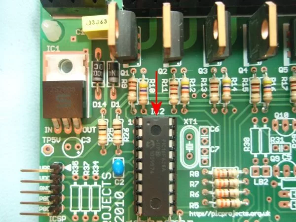
The heart of the LED chaser is the PIC 16F628A microcontroller, IC2. The program that runs on this chip controls the LEDs / MOSFET drivers attached to the output port pins. Resistors R1 thru R8 limit the current through LED1 – LED8 to a safe level that won’t damage the PICs I/O ports or LEDs. These LEDs are provided to monitor the main channel outputs, they can be omitted them if this feature isn’t needed.
Resistor R25 provides a pull-up for the input connected to switch S1. R26 pulls up the PIC’s MCLR reset signal during normal operation while allowing the input to be raised to 12.5 volts during in-circuit programming. The ICSP header provides connection for an ICSP programmer such as a PICkit2 making it easy to reprogram the PIC without removing it from the PCB.
Power is supplied to the circuit through the 3-way terminal block and must be smooth DC between 9 and 18 volts. The PIC requires a precisely controlled 5 volt supply and this is provided by IC1, a 7805 3-terminal, 5 volt regulator. Typical current drawn by the circuit with all LEDs on is only around 100mA so the voltage regulator doesn’t require any additional heatsink. Capacitor C1 stabilizes the regulator. Capacitors C2 / C4 are used to decouple the 5 volt power supply to the board. Diode D1 protects the circuit from accidental reverse polarity of the input voltage. Diode D14 protects the regulator and is only really needed if you will be using the ICSP feature (doesn’t hurt to fit it anyway)
The power output stage comprises eight STP36NF06 N-Channel MOSFETs. These are logic level devices with a low (logic level) gate threshold making them suitable for driving from a PIC output. The 120R gate resistors limit the current during switching, the 47K gate pull-down resistors prevent the MOSFETs from turning on during power up and also from ESD (electro-static discharge).
Although rated at maximum of 30amps and 60 volts source/drain voltage, since the MOSFETs are being used without any heatsink do not exceed 2 amps per channel. In addition to this the connectors and PCB track sizing also limit the maximum current per channel to 2 amps.
DO NOT EXCEED 2 AMPS per CHANNEL
Additional information about PCB480C
Notes:
- The 3-way terminal block supplied with the kit is rated for 20 amps per terminal. There are two terminals connected to V- (Ground). When operating the board at maximum channel output currents it is good practice to wire both inputs to ground.
- Each channel can handle 3 amps however the combined channel current for the board should not exceed 16 amps in total (2 amps per channel when all channels are active simultaneously)
- The ICSP header allows programming of the PIC while installed in the circuit. It is only required if you intend to connect a programmer to modify the sequences or code. It is not supplied with the kit but is available as an option.
- The board itself requires around 100mA to operate, however, the power supply used will need to be specified to handle the total power required for whatever LED modules / arrays are connected to the MOSFET output channels.
For more detail: 8 Channel PWM Power MOSFET LED Chaser for PIC16F628A
- How does the firmware control the LED intensity?
The firmware drives the LEDs with a 5 bit PWM signal providing each of the 8 LED channels with four levels of intensity; off, dim, mid, bright. - What run modes are available in the software?
The software has sequential, random and manual sequence run modes and allows manual advance to the next sequence in any mode. - Can the selected mode be saved after power loss?
Yes, the selected sequence and mode are saved to non-volatile memory so it will always restart in the selected mode. - What is the maximum current allowed per channel?
You must not exceed 2 amps per channel due to the lack of heatsinks on the MOSFETs and PCB track sizing limits. - Does the board require a specific input voltage range?
Power is supplied through a 3-way terminal block and must be smooth DC between 9 and 18 volts. - What is the purpose of Diode D1?
Diode D1 protects the circuit from accidental reverse polarity of the input voltage. - How many total amps can the board handle when all channels are active?
The combined channel current for the board should not exceed 16 amps in total when all channels are active simultaneously. - Is the ICSP header included in the kit?
No, the ICSP header is not supplied with the kit but is available as an option if you intend to connect a programmer. - Can this project be used with fewer than 8 LEDs?
Yes, you can use it with different sized LEDs, mixed colours, and fewer than 8 LEDs. - What is the typical current drawn by the circuit itself?
Typical current drawn by the circuit with all LEDs on is only around 100mA so the voltage regulator does not require any additional heatsink.