Summary of 7 Segment Display Interfacing with PIC Microcontroller
This tutorial introduces interfacing a 4-digit 7-segment display with a PIC microcontroller using MPLAB and XC8. It explains the differences between LCDs and 7-segment displays, highlighting the latter's suitability for numeric data in low-light conditions. The article details the internal structure of common cathode 7-segment modules, the wiring logic for multiplexing four digits using segment pins (A-DP) and digit select pins (D0-D3), and recommends using pre-made modules to avoid complex soldering.
Parts used in the 4-digit 7-Segment Display Interfacing Project:
- PIC Microcontroller
- 16x2 LCD Display (for comparison)
- 7-Segment Display Module
- 4-Digit 7-Segment Display Module
- Common Cathode Seven Segment Display
- MPLABX IDE
- XC8 Compiler
This is our 8th tutorial of Learning PIC microcontrollers using MPLAB and XC8. We have come up all the way from installing MPLABX to using a LCD with PIC MCU. If you are new here, then look at previous tutorials where you can learn timers, blinking LED, interfacing LCD etc.. You can find all our PIC Tutorials here. In our last tutorial we saw how we can generate Custom characters with our 16*2 LCD display, now let us equip our self with another type of display module called the 7-segment display and interface it with PIC Microcontroller.
Although 16×2 LCD is much more comfortable than 7-segment display but there are few scenarios where a 7-segment display would come in handier than a LCD display. LCD suffers from the drawback of having low character size and will be overkill for your project if you are just planning to display some numeric values. 7-segments also have the advantage against poor lighting condition and can be viewed from lager angles than a normal LCD screen. So, let us start knowing it.
7-Segment and 4-Digit 7-Segment Display Module:
7 Segment Display has seven segments in it and each segment has one LED inside it to display the numbers by lighting up the corresponding segments. Like if you want the 7-segment to display the number “5” then you need to glow segment a,f,g,c, and d by making their corresponding pins high. There are two types of 7-segment displays: Common Cathode and Common Anode, here we are using Common Cathode seven segment display. Learn more about 7 segment display here.
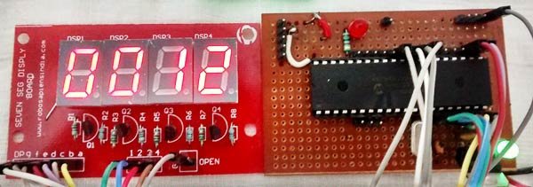
Now we know how to display our desired numeric character on a single 7-segment display. But, it is pretty evident that we would need more than one 7-segment display to convey any information that is more than one digit. So, in this tutorial we will be using a 4-digit 7-Segment Display Module
As we can see there are Four Seven Segment Displays connected together. We know that each 7-segment module will have 10 pins and for 4 seven segment displays there would be 40 pins in total and it would be hectic for anyone to solder them on a dot board, so I would highly recommend anyone to buy a module or make your own PCB for using a 4-digit 7-segment display. The connection schematic for the same is shown below:
To understand how 4-digit seven segment module works we have to look into the above schematics, as shown the A pins of all four display is connected to gather as one A and the same for B,C…. upto DP. So, basically if trigger A on, then all four A’s should go high right?
But, that does not happen. We have additional four pins from D0 to D3 (D0, D1, D2 and D3) which can be used to control which display out of the four should go high. For example: If I need my output to be present only on the second display then only D1 should be made high while keeping other pins (D0, D2, and D3) as low. Simply we can select which display has to go active using the pins from D0 to D3 and what character to be display using the pins from A to DP.
For more detail: 7 Segment Display Interfacing with PIC Microcontroller
- Why choose a 7-segment display over an LCD?
7-segment displays are better for showing numeric values, offer larger character sizes, and perform well in poor lighting or wide viewing angles. - What type of 7-segment display is used in this tutorial?
The tutorial uses a Common Cathode seven segment display. - How many segments does a standard 7-segment display contain?
A 7-segment display contains seven segments, each having one LED inside it. - How do you display the number 5 on a 7-segment display?
You need to glow segments a, f, g, c, and d by making their corresponding pins high. - Why is a module recommended over soldering individual displays?
Soldering four separate displays would require 40 pins total, which is very hectic compared to using a single module or PCB. - How does the D0 to D3 pin control work?
These pins select which of the four displays becomes active; only the specific D pin corresponding to the desired display should be made high. - What happens if all A pins are triggered simultaneously?
All four A segments across the different displays will light up, but digit selection pins determine which specific display shows the character.