Summary of LabVIEW motion controller using pic microcontroller
This Lab 6 tutorial explains multiplexing four common anode seven-segment displays using a PIC16F628A microcontroller to save I/O pins. Instead of dedicating seven pins per display, segments share PORTB via current-limiting resistors. Four PNP transistors act as switches controlled by PORTA (RA0-RA3) to sequentially activate each display's common anode. By refreshing the digits rapidly, all appear illuminated simultaneously.
Parts used in the Multiplexed Seven Segment Display Project:
- PIC16F628A microcontroller
- Four common anode seven segment LED displays
- Four PNP transistors
- Current limiting resistors (Rs)
- Vcc power supply
 That’s why a multiplexing technique is used for driving multiple seven segment displays. This tutorial shows how to multiplex 4 common anode type seven segment LED displays with a PIC16F628A microcontroller.
Circuit Diagram
The theory behind the multiplexing technique is simple. All the similar segments of multiple LED displays are connected together and driven through a single I/O pin. In the circuit below, the seven segments are connected to PORTB through current limiting resistors Rs. A particular segment is active when the corresponding PORTB pin is low. However, it will not glow until it’s anode is connected to Vcc. You can see the anodes of the four LED displays are not directly connected to Vcc. Instead, 4 PNP transistors are used as switches to connect or disconnect the anode terminals from Vcc.
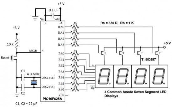 When the base of the PNP transistor is low, the transistor conducts and corresponding digit’s common anode is connected to Vcc. Therefore, the transistor selects which displays is active. The conduction of the transistors are controlled by RA0 through RA3 pins of PORTA. Suppose, if we want to display 7 in the units digit place, then segments a, b, and c should be turned on first (which means RB0, RB1, RB2 are 0 and RB3-RB6 are 1) and then RA0 should be pulled low (while keeping RA1-RA3 high) so that only units digit display will be active. In order to display all 4 digits, each seven-segment display is activated sequentially using an appropriate refresh frequency so that it will appear that all the them are turned on at the same time.
- Why is multiplexing used for driving multiple seven segment displays?
Multiplexing saves resources because driving 4 displays individually requires 28 I/O pins, which mid-range PIC microcontrollers cannot afford. - How are the similar segments of multiple LED displays connected?
All similar segments are connected together and driven through a single I/O pin on PORTB. - What component is used to connect or disconnect the anode terminals from Vcc?
Four PNP transistors are used as switches to manage the connection between the anode terminals and Vcc. - When does a particular segment become active?
A segment becomes active when its corresponding PORTB pin is low and its anode is connected to Vcc. - Which microcontroller pins control the conduction of the transistors?
The base of the PNP transistors is controlled by RA0 through RA3 pins of PORTA. - How do the transistors select which display is active?
When the base of a PNP transistor is low, it conducts, connecting that specific digit's common anode to Vcc. - Why does the display appear to be turned on at the same time?
Each seven-segment display is activated sequentially using an appropriate refresh frequency.