
Summary of 600W – 230VAC – HIGH VOLTAGE DC MOTOR SPEED CONTROLLER – HEATER CONTROLLER – LAMP/LED DIMMER
This project is a high-voltage PWM source and DC motor speed controller supporting up to 330 V DC and 2 A (600 W). It offers adjustable PWM frequency and duty cycle (0–99%), suitable also as a heater controller, LED/lamp dimmer, and general high-voltage PWM driver. The board accepts 100–250 VAC or 100–330 VDC input, includes protections (fuse, inrush NTC, current sense), EMI filtering, and uses an FBA42060 IPM and SG3525 PWM generator.
Parts used in the 600W High Voltage DC Motor Speed Controller:
- FBA42060 Intelligent Power Module (IPM)
- SG3525 PWM Generator IC
- BC847 transistor (Q1)
- 5V regulator (U1)
- Trimmer pot PR1 (frequency adjust)
- Pot P1 (PWM duty cycle adjust)
- Fuse (F1)
- NTC inrush current limiter (R1)
- DC bus filter capacitors (C7, C8)
- EMI capacitors (C2, C6)
- Logic supply filter capacitors (C3, C4)
- Current sense resistor (R12)
- Temperature monitor NTC divide resistor (R3)
- Pull-up resistor for Fault (R2)
- Power LED (D1)
- Connector CN1 (fault/logic connector)
- Connector CN2 (AC or DC load voltage supply)
This is a very powerful DC Motor speed controller for DC motors up to 330V DC and current up to 2A. Basically, the project is a high voltage PWM source with adjustable frequency and adjustable PWM duty cycle range 0 to 99%. The board has been designed considering many applications and the circuit can be used as a heater controller, DC Motor speed controller, LED dimmer, Lamp dimmer, and High voltage PWM driver. The circuit can handle load up to 600W (330V DC @ 2A). The operating input supply is 100V AC to 250V AC or 100V to 330V DC. It is important to provide the input supply as per the operating power supply of the load. Trimmer pot PR1 is provided to adjust the frequency, and P1 to adjust the PWM duty cycle.
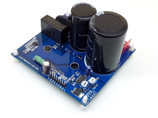
Connector CN2 is used for AC or DC load voltage supply, F1 Fuse for protection, R1 NTC to control inrush-current, C2 and C6 for EMI noise, C7 and C8 DC Bus filter capacitor for load supply, R12 Current sense resistor for overcurrent protection feedback circuit (CSC), R3 Temperature monitor (NTC) divide resistor for temperature feedback output, C3, C4 logic supply filter capacitors, CN1, R2 pull up resistor for Fault (VFO), SG3525 PWM Generator, Q1 BC847 to inverse the PWM, D1 power LED, U1 5V regulator.
FBA42060 – INTELLIGENT POWER MODULE (IPM)
The project is built using the FBA42060 IPM chip. This IPM chip is made for power factor correction, and consists of an inbuilt bridge rectifier, diode for back-EMF protection for inductive loads, IGBT to drive the loads, and IGBT gate driver and on chip NTC temperature monitor.
Read more: 600W – 230VAC – HIGH VOLTAGE DC MOTOR SPEED CONTROLLER – HEATER CONTROLLER – LAMP/LED DIMMER
- What is the maximum voltage and current this controller can handle?
The controller supports up to 330 V DC and up to 2 A (600 W). - What input supplies are supported?
Operating input supply is 100 V AC to 250 V AC or 100 V to 330 V DC. - What is the PWM duty cycle range?
The PWM duty cycle range is adjustable from 0 to 99%. - Which component generates the PWM signals?
The SG3525 PWM generator IC provides PWM signals. - Which module is used to drive the power stage?
The FBA42060 intelligent power module (IPM) is used for the power stage. - What protections and monitoring are included?
The board includes a fuse, NTC inrush limiter, current sense resistor for overcurrent feedback, and an on-chip NTC temperature monitor in the IPM plus a temperature divide resistor R3. - Can this circuit be used as an LED or lamp dimmer?
Yes, the article states the circuit can be used as an LED dimmer and lamp dimmer. - How do you adjust the PWM frequency?
Frequency is adjusted using trimmer pot PR1. - How do you adjust the PWM duty cycle?
PWM duty cycle is adjusted using pot P1. - What components filter EMI and stabilize the DC bus?
C2 and C6 are for EMI noise filtering, and C7 and C8 are DC bus filter capacitors.

