Summary of 2.5 GHz Frequency counter using PIC16F870
This article details a high-performance, homebrew RF frequency counter capable of measuring up to 2.5 GHz with 1kHz resolution. It features a PIC16F870 microcontroller, an LMX2322 prescaler, and six multiplexed LED displays. The device includes an RS232 interface for computer connectivity and jumpers to subtract IF offsets (455 kHz or 10.7 MHz) for radio receiver testing. Its high sensitivity allows measurement with just a few millivolts of RF input.
Parts used in the 2.5 GHz Frequency Counter:
- PIC16F870 microcontroller
- LMX2322 prescaler circuit
- Six LED displays
- 13MHz crystal oscillator
- Variable capacitor C11
- PNP transistor
- 9-pol female dsub connector
- Jumpers SW1 and SW2
- Resistors for 50 ohm impedance matching
- Attenuator resistors
Background
It is time to update the frequency counter again.
A frequency counter is one of the most important measuring tool we need as homebrewers of RF electronic.
This frequency counter has very high performance and still is very easy to build and to use. Anyone can build it and have fun.
The counter is based around 6 LED displays which will present the frequency with 1kHz resolution.

I don’t find it necessary to have more digits.
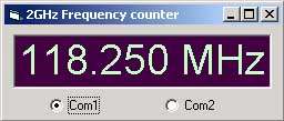
The frequency will be presented on the LED display and at the same time also sent on the RS232 line.
If you want you can connect the counter to a computer and display the frequency information there.
In that case you don’t need any LED displays. This frequency counter is very sensitive and need just a few millivolt of RF to measure the frequency. You can easy connect it to any oscillator or you can make a pic-up coil to probe the oscillator. (More about this later)
To make this counter even more useful and intelligent, I have added an option for offsetting the frequency showed on the LED display with 2 jumpers SW1 and SW2. The offset calculation is easy activated with 2 jumpers, one for 455 kHz and one for 10.7 MHz.
It works like this:
Imagine you have a radio receiver and you wish to display the receiving frequency. As you know the oscillator in a radio receiver works 455 kHz or 10.7 MHz above the receiving frequency. The 455 kHz and 10.7 MHz difference is called IF (Intermediate Frequency).
So to display correct frequency, the counter needs to subtract the incoming frequency with 455 kHz or 10.7 MHz depending on your receiver system. 455 kHz is used in (narrow) band units and AM reception. 10.7 MHz is used in WB (wide band) and commercial receivers.
Example:
You have a radio and you want to listen at 100.0 MHz (the IF is 10.7 MHz) The oscillator will be oscillating 10.7 MHz above the 100 MHz, so the oscillator is at 110.7 MHz. If you would measure the frequency with an ordinary counter you would get 110.7 MHz on the LED display but, by activating the offsetting function this counter will subtract and display 100.0 MHz. The offset calculation is easy activated with 2 switches, one for 455 kHz and one for 10.7 MHz.
Boy, I wish I had this counter when I was building my first receiver for aircraft-band, which was manually tuned and not very stable.
Hardware and schematic
Most HF frequency counters need a prescaler in front of the counter unit.
In this case I use a circuit called LMX2322 which has prescaler function.
Of course you can use any prescaler as long as it divides by 64.
I have chosen this circuit since I have them and they are very sensitive and easy to work with.
The sensitivity is so good that in many cases you will need a attenuator based on a few resistors to make it work properly. More details later.
The prescaler has two differential inputs called Fin and /Fin.
If you wish you can connect /Fin to ground and use only Fin going to pin 8. Two 100 resistor forms 50ohm for impedance input matching.
The output of the prescaler (CPo) is a TLL lever where the frequency is divided by 64.
The signal then enters the microcontroller into its counting register (RC0). The microcontroller count the input pulses during 64mS.
The accuracy of this counter is set by the frequency of the 13MHz crystal.
The crystal frequency can be fine tuned by a variable capacitor C11 to obtain very high accuracy.
The frequency is displayed on the 6 LED display in multiplexed way. It means that only one LED is turned on at the same time.
First LED 1 is lightning, then LED 2 and so one. This goes so fast that it appears that all are lightning. During the 64mS counting, the LEDs are off to decrease noise on the power line. When the display are updated the info is also sent on the RS232 line (RC6).
A PNP transistor convert the TTL voltage to RS232 voltage. The connector is a standard 9-pol female dsub which will fit into any computers comport. If you are not going to use this part you don’t have to build it.
Frequency offset by SW1 and SW2.
When SW1 and SW2 is not activated the counter show actual frequency.
When SW1 is activated (short circuit) the counter subtract the measured frequency with 455 KHz.
When SW2 is activated (short circuit) the counter subtract the measured frequency with 10.7 MHz.
PCB
| fq232.pdf | PCB file for 1GHz frequency counter (pdf). |
Above you can download a (pdf) filer which is the black PCB.
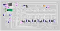
Above you will find two pic showing the assembly of all components on the same board.
The scale of the pdf is 1:1 and the two picture are magnified 4 times.
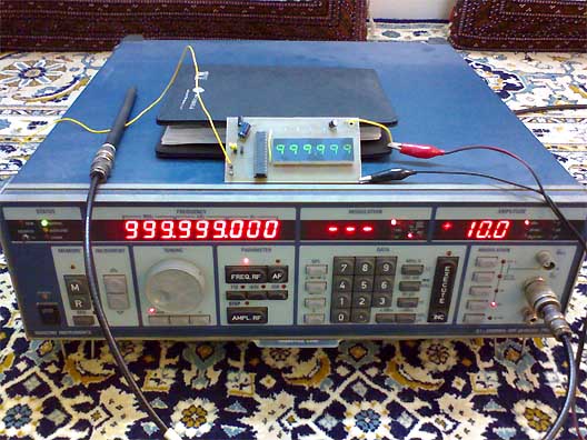
This is how the real board should look when you are going to solder the components.
It is a board made for hole mounted components and at the bottom layer you will have some surface mounted components.
Grey area is cuppar and each component is draw in different colours all to make it easy to identify for you.
Click on the two picw to enlarge them.
Sensitivity of input signal
Table below show my measurements of the sensitivity of this unit.
I have not measured below 60MHz and the upper limit is 220MHz since my generator ends there.
This counter should be able to measure up to 2.5 GHz easy.
The input signal is terminated at the prescaler with 50 ohm (2 x 100 ohm resistor parallell)
This is to match impedances and to give dBm measurements.
|
Frequency (MHz)
|
mV rms
|
uW (into 50 ohm)
|
dBm (into 50 ohm)
|
|
60
|
90
|
160
|
-8.0
|
|
80
|
60
|
69
|
-11.6
|
|
100
|
48
|
46
|
-13.3
|
|
120
|
40
|
32
|
-15.0
|
|
140
|
33
|
22
|
-16.6
|
|
160
|
27
|
15
|
-18.2
|
|
180
|
24
|
12
|
-19.2
|
|
200
|
24
|
12
|
-19.2
|
|
220
|
24
|
12
|
-19.2
|
Attenuator
Attenuator is some resistor to lower the input power and still obtain matching impedance.
It is very simple to build and works really good.
The picture at right show you how to build it and how to calculate damping.
You can serial connect several attenuators if you need to.
This attenuator damp 6dB.
6dB means that tge output power is only 1/4 of the input power.
It also means that the output voltage is 1/2 of the input voltage.
As you see I have used 100ohm resistor becasue I use SMD and they are cheap and accurate.
Windows software
|
Download windows software
fq.zip (1.41Mb) |
|
|
Click here to go to the software download page!
|
|
Unzip it and run setup, that is all. Just install the program and connect the cable to the frequency counter.
Make sure you set right comport in the software (Com1 or Com2).
If you want to make your own software you should know that the baud rate of the transmission is 1200 baud, 8 bit, 1 stop and no parity.
The PIC send data like this:
If the frequency is 128.250MHz the string will be : 01h, 02h, 08h, 2eh, 02h, 05h, 00h
Download PIC16F870 programs (INHX8M format)
The zip file contains hex file made for this project.
| led_counter.zip | Software 999MHz with 1kHz resolution (the hex files are zipped!) |
| led_counter_uhf.zip | Software 2.5 GHz with 10kHz resolution(the hex files are zipped!) |
Component support
This project has be constructed to use standard (and easy to find) components.
You can find all necessary components at my component page.
Final word
This part describes the construction of a very powerful frequency counting tool.
I hope you will have lot of use of your counter.
Do please send a photo of your construction and I put it onto the coming gallery.
You can always mail me if there is anything unclear.
I wish you good luck with your projects and thanks for visit my page.
Photo Gallery
Some assembled counters people has mailed me. Please mail me more.
Source: 2.5 GHz Frequency counter using PIC16F870
- What is the maximum frequency this counter can measure?
The counter should be able to measure up to 2.5 GHz easily. - How does the offset function work for radio receivers?
Activating SW1 subtracts 455 kHz and activating SW2 subtracts 10.7 MHz from the measured frequency. - Can I connect this counter to a computer without LED displays?
Yes, you can connect it via the RS232 line to display frequency information on a computer instead of using LEDs. - What is the required RF input level for accurate measurement?
The counter is very sensitive and needs just a few millivolts of RF to measure the frequency. - How is the accuracy of the counter determined?
The accuracy is set by the frequency of the 13MHz crystal and can be fine-tuned using variable capacitor C11. - What are the transmission settings for the RS232 connection?
The baud rate is 1200 baud, 8 bit, 1 stop, and no parity. - Which components form the 50 ohm input impedance matching?
Two 100 ohm resistors form the 50 ohm impedance input matching at the prescaler. - Does the project support different resolution modes?
Yes, there are software options for 999MHz with 1kHz resolution and 2.5GHz with 10kHz resolution.