Summary of 1KHZ TO 20MHZ LOW POWER OSCILLATOR
This compact, low-power 1 kHz–20 MHz precision oscillator runs from a single 5 V supply, provides a rail-to-rail CMOS square-wave output with ~50% duty cycle, and offers ≤1.5% frequency error. Frequency is set by a multi-turn trimmer and a DIV jumper (divide by 1, 10, or 100) for three output ranges. It can drive up to 50 mA and supports 5 kΩ/10 pF loads, fast start-up, and small PCB dimensions.
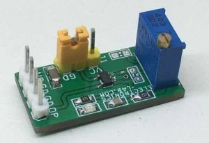
Parts used in the 1 kHz to 20 MHz Low Power Oscillator:
- Oscillator IC with CMOS output driver
- Multi-turn trimmer potentiometer (frequency adjust)
- Jumper (J1) for master frequency divider
- Printed Circuit Board (27.31 x 13.18 mm)
- Power supply connector for 5 V DC
- Passive components (resistors, capacitors for oscillator network)
- Output connector/pins capable of driving 5 kΩ and 10 pF loads
- Decoupling capacitor(s)
- Silkscreen/labels for PR1 and J1
This is a precision, low power oscillator that occupies very little space. The oscillator frequency is adjustable using an onboard multi-turn trimmer potentiometer. The output of the circuit is very accurate and has a 1.5% frequency error. The project operates with a single 5V power supply and provides a rail-to-rail, 50% duty cycle square wave output. The CMOS output driver of the chip ensures fast rise/fall times and rail-to-rail switching. A multi-turn trimmer provided to adjust the master oscillator frequency between 1Khz to 20Mhz. Jumper provided for the three-state DIV input which determines the master clock is divided by 1, 10,100 before the output, providing three frequency ranges spanning 1Khz to 20Mhz. The output of the project can drive 5 KΩ and/or 10pF loads. The output of the project is limited to 50mA.
JUMPER/SUNT J1 SETTINGS
- J1 Connected to VCC = Frequency Output 1Khz to 200Khz (Set PR1)
- Jumper J1 Open = Frequency output 10Khz to 2Mhz (Set PR1)
- Jumper J1 GND= Frequency Output 100Kz to 20Mhz (Set PR1)
FEATURES
- Operating Power Supply 5V DC (8mA)
- Multi-turn trimmer to set the frequency
- Output Current 50mA Maximum
- Jumper J1, Master Frequency Divider, 1, 10, 100
- Jumper J1 GND =N1, VCC=N100, Jumper Open N=10
- Output Frequency 1Khz to 20Mhz
- Frequency Error ≤1.5% Max, 5kHz to 10MHz
- 50% ±1% Duty Cycle 1kHz to 2MHz
- 50% ±5% Duty Cycle 2MHz to 10MHz
- Fast Start-Up Time: 50μs to 1.5ms
- PCB Dimensions 27.31 x 13.18mm
Read more: 1KHZ TO 20MHZ LOW POWER OSCILLATOR
- What supply voltage does the project require?
The project operates from a single 5V DC supply (8 mA). - How is the output frequency adjusted?
The output frequency is adjusted using an onboard multi-turn trimmer potentiometer (PR1). - What frequency range does the oscillator cover?
The oscillator provides output frequencies from 1 kHz to 20 MHz. - How does the J1 jumper affect frequency ranges?
J1 selects the master frequency divider: J1 to VCC gives divide by 100 (1 kHz to 200 kHz), J1 open gives divide by 10 (10 kHz to 2 MHz), J1 to GND gives divide by 1 (100 kHz to 20 MHz). - What is the output duty cycle accuracy?
The output is 50% ±1% duty cycle from 1 kHz to 2 MHz and 50% ±5% from 2 MHz to 10 MHz. - What is the specified frequency accuracy?
The output has a frequency error of ≤1.5% (specified for 5 kHz to 10 MHz). - What output drive capability does the circuit have?
The CMOS output can drive loads of 5 kΩ and/or 10 pF and is limited to 50 mA maximum output current. - What is the start-up time of the oscillator?
Fast start-up time ranges from 50 μs to 1.5 ms. - What are the PCB dimensions?
The PCB measures 27.31 x 13.18 mm.