
Summary of 1000 steps Servo motor
This article details a DIY project converting a standard servo motor into a continuous rotation stepper-like device using an Arduino and H-bridge. The author removes the internal electronics, retaining only the potentiometer and DC motor, then wires them to control direction and speed via PWM. The provided code reads the potentiometer's analog value to determine distance from a target position (500 steps) and adjusts motor behavior accordingly, allowing for 1000-step precision within a 0-180° range.
Parts used in the 1000 Steps Servo Motor Project:
- Servo motor (normal or microservo)
- Arduino board
- USB cable
- H-bridge (specifically L293D mentioned)
- 100nF capacitor (optional, symbol 104)
- Breadboard
- Wires
- Soldering iron
- Small screwdriver
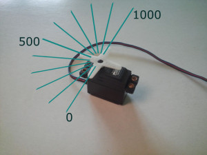
In many project like CNC machines people use stepper motors. They are probably always more expensive than servos. They can rotate 360°, 1 step = 1,8° (mostly). Servos can rotate only from 0° to 180°, 1 step = 1°. But why are they working this way, inside them we will find potentiometer which rotates as servo (up to 180°), but have 1024 steps.
I’ve started to think about it.
Step 1: What I have used
Picture of What I have used
20160611_195959_HDR.jpg
20160611_200532_HDR.jpg
20160611_200916_HDR.jpg
Parts that I’ve used to make a prototype version:
Servo (normal, you can also use microservo),
Arduino and USB cable,
H-bridge (I have L293D, any other will work too),
100nF capitator (optonal, symbol: 104),
Breadbord,
Wires,
Soldering iron and small screwdriver.
Firstly, let’s prepare servo:
Open it and remove the electronics. Leave the potentiometer and DC motor. If your engine don’t have capitator I prefer to solder one to it, that is not needed, but with capitator your motor will have more power.
Than solder the wires to engine and potentiometer, so you can put them into breadbord.
Step 2: Breadbord circuit
Picture of Breadbord circuit
Sterownik.jpg
20160611_201431_HDR.jpg
Build a circuit like you see in the picture. If you have different H-bridge than I have used you should find how to connect it.
Pins:
Analog pin 1 checks the potentiometer,
Digital pins 2 and 4 sets the direction of rotation,
Digital pin 3 set motor speed (PWM, symbol on Arduino board: ~ ),
+5V and GND powering engine and potentiometer (WARNING: in microservo 5V could damage motor).
Step 3: Program
Picture of Program
Serial2.png
// 1000 steps Servo by TheSuperSewcio
#define pos 500 //servo position, use 10 – 1010,
int distance; //potentiometer may have trouble with values > 1010 or < 10
void setup() {
Serial.begin(9600);
pinMode(2, OUTPUT);
pinMode(3, OUTPUT);
pinMode(4, OUTPUT);
}
void loop() {
Serial.println(analogRead(1));
distance = analogRead(1) – pos;
if(distance < 0){
distance = -distance;
}
if(distance == 0){
digitalWrite(3, LOW);
}else{if(distance < 100){ //reduces speed 100 steps before target
analogWrite(3, distance + 50); //minimum speed: 50
}else{
digitalWrite(3, HIGH);
}}
if(analogRead(1) > pos){
digitalWrite(4, LOW); //set direction of rotation
digitalWrite(2, HIGH);
}else{if(analogRead(1) == pos){
digitalWrite(2, LOW); //stops motor
digitalWrite(4, LOW);
}else{
digitalWrite(2, LOW);
digitalWrite(4, HIGH);
}}
}
Your servo may be different from my, if for some reason something isn’t working try to change values in lines 21 and 22.
As you can see here, servo position is sometimes exactly 500, sometimes 499 – 501. It depends on servo gearbox and potentiometer quality.
For More Details: 1000 steps Servo motor
-
What parts are required to build the prototype version?
You need a servo, Arduino, USB cable, H-bridge, optional 100nF capacitor, breadboard, wires, soldering iron, and small screwdriver. -
How do you prepare the servo for this project?
Open the servo, remove the internal electronics leaving only the potentiometer and DC motor, and solder wires to both components. -
Can I add a capacitor to improve motor performance?
Yes, if your engine does not have one, you can solder a capacitor to it to provide more power to the motor. -
Which Arduino pins are used for the circuit connections?
Analog pin 1 checks the potentiometer, digital pins 2 and 4 set the direction, and digital pin 3 sets the motor speed via PWM. -
Is there a voltage warning for microservos?
Yes, applying 5V could damage the motor in a microservo, so caution is advised when powering it. -
What is the default target position value in the program?
The default position is set to 500, which corresponds to the middle of the potentiometer range (10 to 1010). -
Why might the servo position fluctuate slightly around the target?
The position may vary between 499 and 501 depending on the quality of the servo gearbox and potentiometer. -
How does the code handle the motor when the distance is zero?
If the distance is zero, the code sets digital pin 3 to LOW to stop the motor.

