
Summary of 10 steps to selecting a microcontroller
Selecting the right microcontroller requires analyzing system requirements before hardware choices. The article outlines ten steps, starting with defining hardware interfaces like communication protocols (USB, Ethernet) and I/O types (digital, analog, PWM). This process ensures sufficient program space and pin counts are accounted for in the final selection.
Parts used in Microcontroller Selection:
- Hardware block diagram
- Flowchart
- Communication interfaces (USB, I2C, SPI, UART, Ethernet)
- Digital inputs and outputs
- Analog to digital inputs
- PWMs
Selecting the right microcontroller for a product can be a daunting task. Not only are there a number of technical features to consider, there are also business case issues such as cost and lead-times that can cripple a project. At the start of a project there is a great temptation to jump in and start selecting a microcontroller before the details of the system has been hashed out. This is of course a bad idea. Before any thought is given to the microcontroller, the hardware and software engineers should work out the high levels of the system, block diagram and flowchart them and only then is there enough information to start making a rational decision on microcontroller selection. When that point is reached, there are 10 easy steps that can be followed to ensure that the right choice is made.
Step 1: Make a list of required hardware interfaces
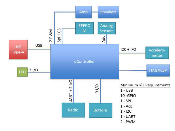
Using the general hardware block diagram, make a list of all the external interfaces that the microcontroller will need to support. There are two general types of interfaces that need to be listed. The first are communication interfaces. These are peripherals such as USB, I2C, SPI, UART, and so on. Make a special note if the application requires USB or some form of Ethernet. These interfaces greatly affect how much program space the microcontroller will need to support. The second type of interface is digital inputs and outputs, analog to digital inputs, PWM’s, etc. These two interface types will dictate the number of pins that will be required by the microcontroller. Figure 1 shows a generic example of a block diagram with the i/o requirements listed.
For more detail: 10 steps to selecting a microcontroller
- What is the best way to start selecting a microcontroller?
Engineers should first work out high-level system details, create a block diagram, and flowchart the system. - Why is it bad to select a microcontroller before system details are hashed out?
Jumping in early is a bad idea because there is not enough information to make a rational decision. - How many steps are suggested to ensure the right choice is made?
The article states there are 10 easy steps that can be followed. - What are the two general types of interfaces that need to be listed?
The two types are communication interfaces and digital inputs/outputs, analog to digital inputs, and PWMs. - Which interfaces greatly affect how much program space the microcontroller needs?
Interfaces such as USB or some form of Ethernet greatly affect program space requirements. - Can you use a generic example of a block diagram for i/o requirements?
Yes, Figure 1 shows a generic example of a block diagram with the i/o requirements listed.
